00198171-02_Technical_Training_FSE_TX-Series_EN.pdf - 第122页
8 Control and Communication 8.3 MGCU and MHCU 122 Technical Training FSE SIPLACE TX-Series 01/2018 GCAN (Gantry CAN bus) The TX machines run with machine CAN bus also second additional gantry CAN bus. The gantry CAN bus …
8 Control and Communication
8.2 Machine Communication bus Overview
Technical Training FSE SIPLACE TX-Series 01/2018 121
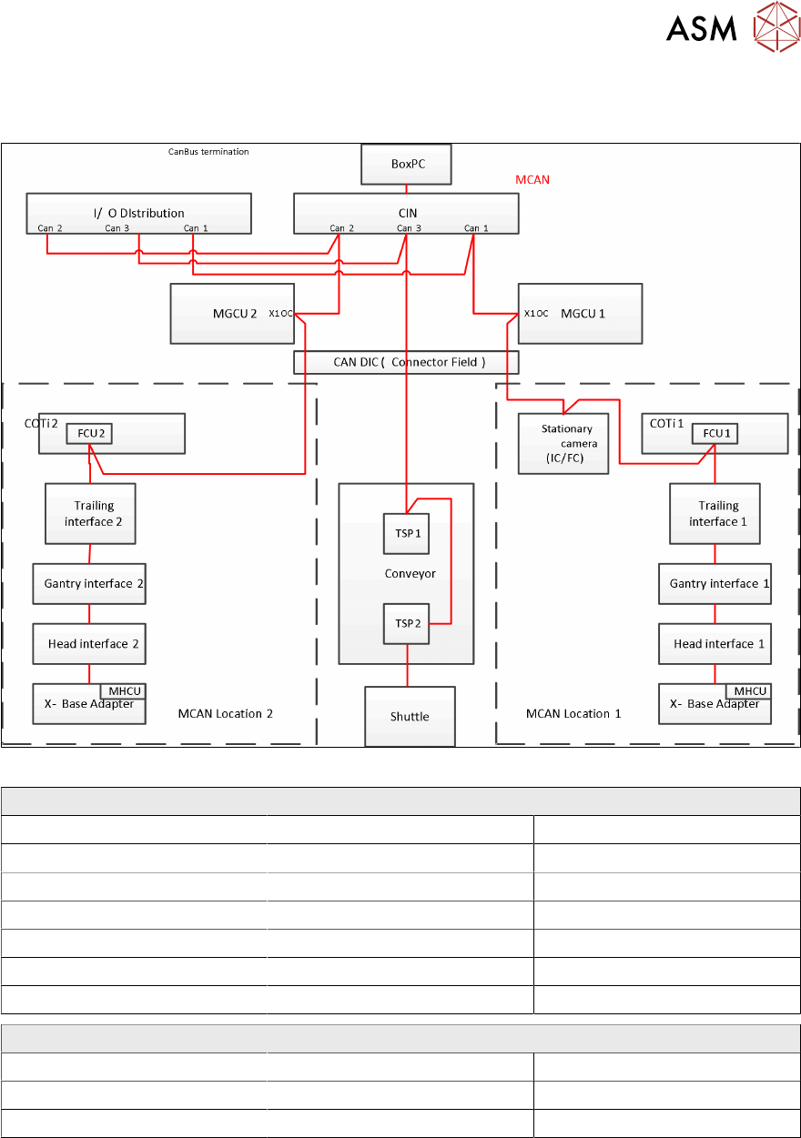
Overview CAN bus
Overview of machine CAN bus participants
CAN bus loop 1 CAN bus loop 2 CAN bus loop 3
MGCU 1 (primary axis) MGCU 2 (primary axis) I/O unit (input-/ output module)
MHCU1 (head axis) MHCU1 (head axis) Conveyor controller (TSP)
I/O unit (input-/ output module) I/O unit (input-/ output module) Shuttle extension
Stationary camera COTi2 / FCU2
COTi1 / FCU1
CIN Box CIN Box CIN Box
Head CAN bus 500KBit/s
Pressure control valve (C&P20) Holding circuit sensor Bottom light sensor
DP station (CPP/C&P20) SCS
Valve block (CPP) EEPROM Z/Star Axis
8 Control and Communication
8.3 MGCU and MHCU
122 Technical Training FSE SIPLACE TX-Series 01/2018
GCAN (Gantry CAN bus)
The TX machines run with machine CAN bus also second additional gantry CAN bus.
The gantry CAN bus provides the communication for synchronization between the Gantry Control
Units (MGCUs) and the Head Control Units (MHCUs).
GCAN bus participants
MGCU 1/2 (main axis) and MHCUs (head axis).
Fast Drive bus (FDB)
Additionally to the machine and gantry CAN bus system, TX machines use a Fast Drive bus (FDB).
Due to the decentralised drive concept, this CAN system is used for the faster data exchange
between MHCUs and MGCUs, providing extremely fast communication to control the axis, using
transfer rates of 20 Mbit/s (in contrast to the MCAN & GCAN bus with 1 Mbit/s).
The FDB enables you to adapt the data for the drives very flexibly or rather to implement new func-
tions.
The FDB is completely independent of the machine CAN bus.
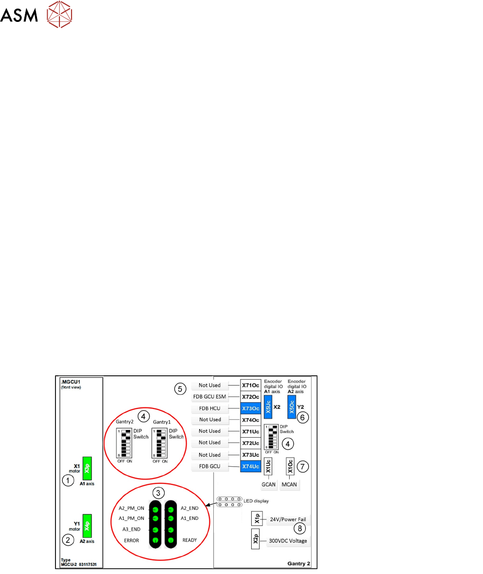
8.3 MGCU and MHCU
MGCU (Modular Gantry Control Unit):
MGCU is used for controlling of the gantry main axes X & Y; it consists of a control module (CM)
and a power module (PM), comparable to the axis card as control module and the servo card as
power module.
Depending on the MGCU type it can control 2 gantry axis (MGCU2) or 3 gantry axis (MGCU3),
MGCU2 is used on TX machine as controller of the main axes (X/Y axis) of gantry (one MGCU2 for
one gantry).
1. X Motor connection
2. Y Motor Connection
3. LEDs
4. DIP Switches
5. BUS connections
6. X/Y Track Signal connector
7. MCAN and GCAN
8. 24V power fail and 300VDC
link
MHCU (Modular Head Control Unit)
MHCU is used for controlling of the head axes (Star/Z) it also consists of a control module (CM)
and a power module (PM).
8 Control and Communication
8.4 Box PC (Control Computer)
Technical Training FSE SIPLACE TX-Series 01/2018 123
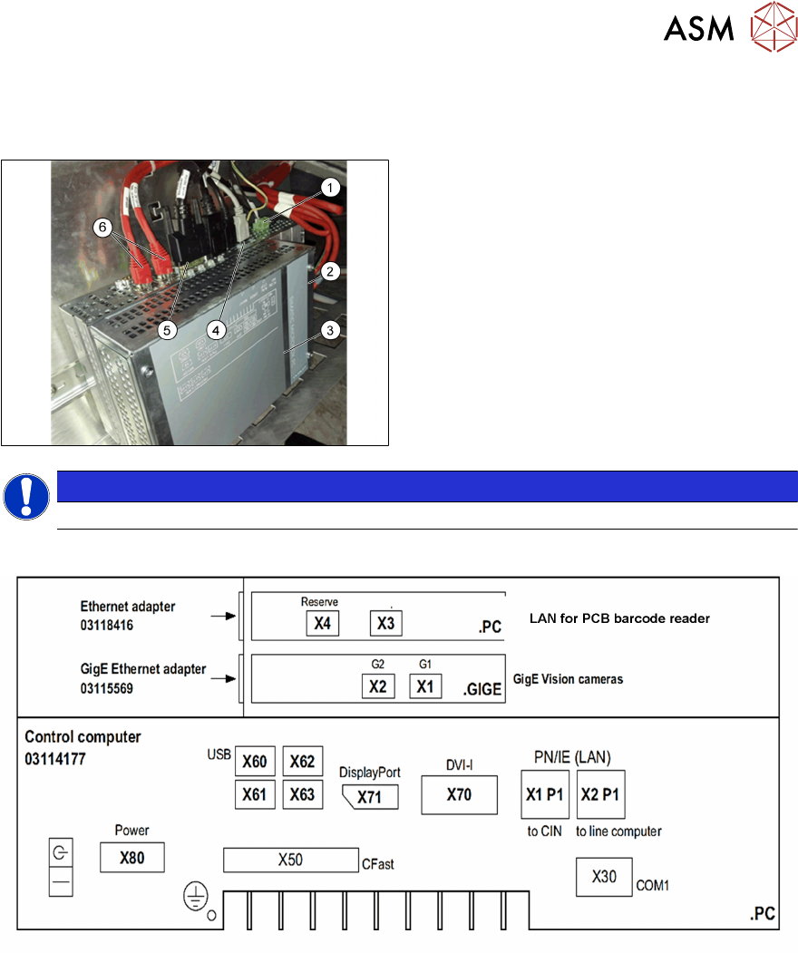
8.4 Box PC (Control Computer)
Box PC 427D
1. Power 24VDC
2. GigE connection
3. Box PC 427D (03114177-xx)
4. USB connectors
5. Display Port for monitor 1
DVI for monitor 2
6. LAN1 CIN‐Box (CAN‐Bus)
LAN2 line computer
NOTICE
After replacing the BoxPc with new one, the station SW needs to be installed.
Control computer SIPLACE TX
Different ports for different monitors, “DisplayPort” (X71) for monitor1 (Power supply side) and
“DVI-I” (X70) for monitor 2.
Before the successful installation of the SW, different displays are shown on each monitor.
8.5 CIN Box
●
In TX-Series machines the, "CAN Interface" CIN [03108598-xx] is used to take over the func-
tion of CAN Card in the previous machines.
●
CIN located in the SMPS and connected to the BoxPC-427D via a LAN cable.
●
For TX machine, the CAN termination on CIN always setting as "OFF".