00198171-02_Technical_Training_FSE_TX-Series_EN.pdf - 第124页
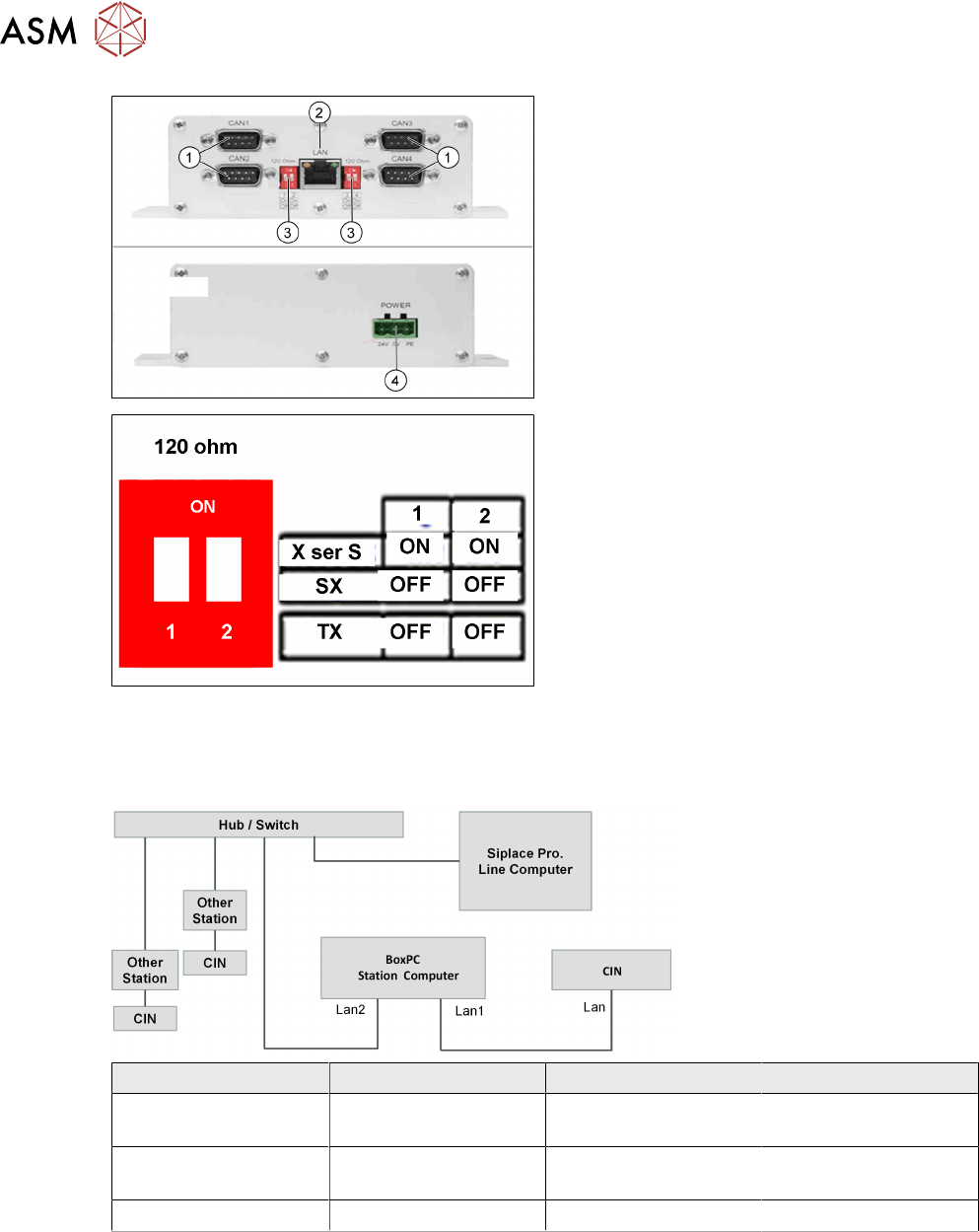
8 Control and Communication 8.6 Network Construction 124 Technical Training FSE SIPLACE TX-Series 01/2018 1. CAN connections 1-4 2. LAN connection 3. DIP switches - setting the terminator of 120 Ohm for CANx- Note : The …
8 Control and Communication
8.4 Box PC (Control Computer)
Technical Training FSE SIPLACE TX-Series 01/2018 123
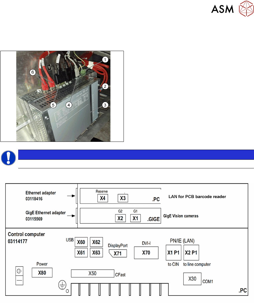
8.4 Box PC (Control Computer)
Box PC 427D
1. Power 24VDC
2. GigE connection
3. Box PC 427D (03114177-xx)
4. USB connectors
5. Display Port for monitor 1
DVI for monitor 2
6. LAN1 CIN‐Box (CAN‐Bus)
LAN2 line computer
NOTICE
After replacing the BoxPc with new one, the station SW needs to be installed.
Control computer SIPLACE TX
Different ports for different monitors, “DisplayPort” (X71) for monitor1 (Power supply side) and
“DVI-I” (X70) for monitor 2.
Before the successful installation of the SW, different displays are shown on each monitor.
8.5 CIN Box
●
In TX-Series machines the, "CAN Interface" CIN [03108598-xx] is used to take over the func-
tion of CAN Card in the previous machines.
●
CIN located in the SMPS and connected to the BoxPC-427D via a LAN cable.
●
For TX machine, the CAN termination on CIN always setting as "OFF".
8 Control and Communication
8.6 Network Construction
124 Technical Training FSE SIPLACE TX-Series 01/2018
1. CAN connections 1-4
2. LAN connection
3. DIP switches - setting the terminator of
120 Ohm for CANx-
Note:
The DIP switch settings (see below) are
valid for both DIP switches.
4. Power Input
DIP switch settings
8.6 Network Construction
Network Construction
IP address Subnet mask Comment
SIPLACE Lan 172.22.xxx.xxx 255.255.0.0 LAN connection on the
computer
CIN 192.168.255.239 255.255.255.224 LAN connection on the
computer
Station computer 192.168.255.249 255.255.255.224
8 Control and Communication
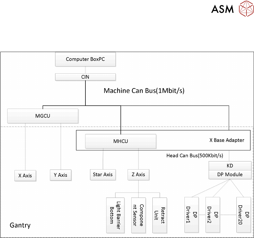
8.7 Axis Control
Technical Training FSE SIPLACE TX-Series 01/2018 125
8.7 Axis Control
Axis Control
8.8 FCU
The FCUs (Feeder Control Unit) on TX machines has the basically functionality:
●
Communication with the feeders and docking of the COT.
●
Control of the tape cutter (moving the pneumatic cylinders in and out, status query of the
sensors).
●
Nozzle changers detection and the nozzle station (forced air valve for the C&P20 and CPP)
control.
●
Query of the sensors for the component/nozzle reject boxes.
During production with (SW1= OFF) the reject bin is recognized by the sensor and signalized by
the LED.
The FCU need to be addressed for the TX see diagram below: