00198171-02_Technical_Training_FSE_TX-Series_EN.pdf - 第57页
5 Component Supply 5.7 Nozzle Changer for C&P20 P/M2 / CPP and Twin Heads Technical Training FSE SIPLACE TX-Series 01/2018 57 5.7 Nozzle Changer for C&P20 P/M2 / CPP and Twin Heads 1. Nozzle changer carrier modul…
5 Component Supply
5.6 Component Supply Pneumatic & Electrical System
56 Technical Training FSE SIPLACE TX-Series 01/2018
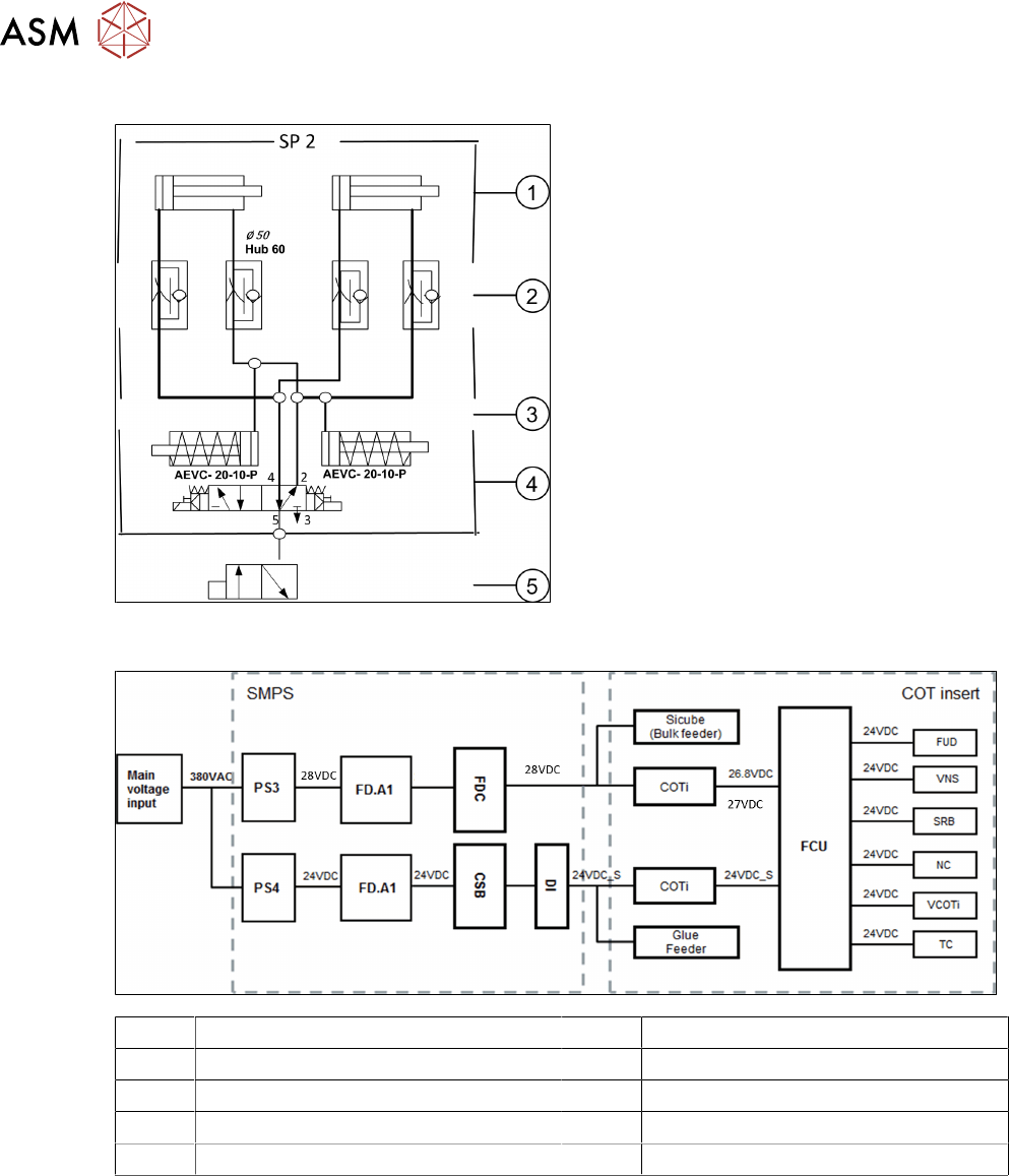
Docking Unit Pneumatic System
1. Pneumatic cylinder for moving the cam
disks
2. Throttle valves for adjusting the speed of
the pneumatic should take approx. 2 –
3seconds for docking and undocking
3. Pneumatic cylinders for ejecting the COT
during the undocking procedure
4. 5/2 way valve for controlling the pneumatic
cylinder
5. Safety valve in case of electrical faults
5.6.2 Overview Electrical System
FD.A1 Fuse-/Connecting Board TX VNS Valve Nozzle Station
FDC Fuse and Distribution Connector field SRB Sensor Reject Bin
FCU Feeder Control Unit TC Tape Cutter
COTi COT insert NC Nozzle Changer
FUD Feeder Unlock Device VCOTi Valve COT-insert
5 Component Supply
5.7 Nozzle Changer for C&P20 P/M2 / CPP and Twin Heads
Technical Training FSE SIPLACE TX-Series 01/2018 57
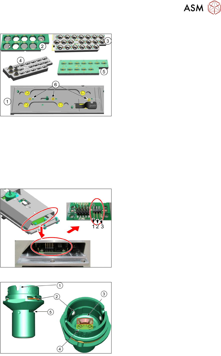
5.7 Nozzle Changer for C&P20 P/M2 / CPP and Twin Heads
1. Nozzle changer carrier module short
2. Magazine type 28xx for CPP
3. Magazine type 40xx for C&P20 P and M2
4. Magazine type 20xx with 20 Nozzles for
CPP
5. Magazine type 20xx for CPP
6. Micro switches for magazine detection
The nozzle changer consists of four magazines. The magazines are seated on a carrier module.
Each magazine is fixed with the help of a snap fastener and can be released with a lever.
Each garage can be configured with different nozzle types. It is allowed to mix all three magazine in
one nozzle changer (12*20xx, 20*20xx and 9*28xx magazine types).
The station software cannot detect if a magazine with 12 garages is inserted or one with 20 gar-
ages. The difference can only be determined when the fiducials are measured.
Each magazine is scanned by 3 micro switches. These are actuated differently for each magazine
type.
The station software automatically detects which magazine types are used and if all magazines are
inserted correctly.
●
Nozzle changer control board settings.
●
The jumper setting is required to make
the nozzle changer compatible to all soft-
ware versions.
●
Setting for CPP and C&P20P is 2-3.
Nozzle ID
1. Nozzle fixing groove with nozzle interface
2. Nozzle ball lock
3. Nozzle barcode to identify the nozzle
type via the PCB camera
4. Nozzle filter
5. Nozzle lock for return and reject
5 Component Supply
5.8 Analysis - Common Error List
58 Technical Training FSE SIPLACE TX-Series 01/2018
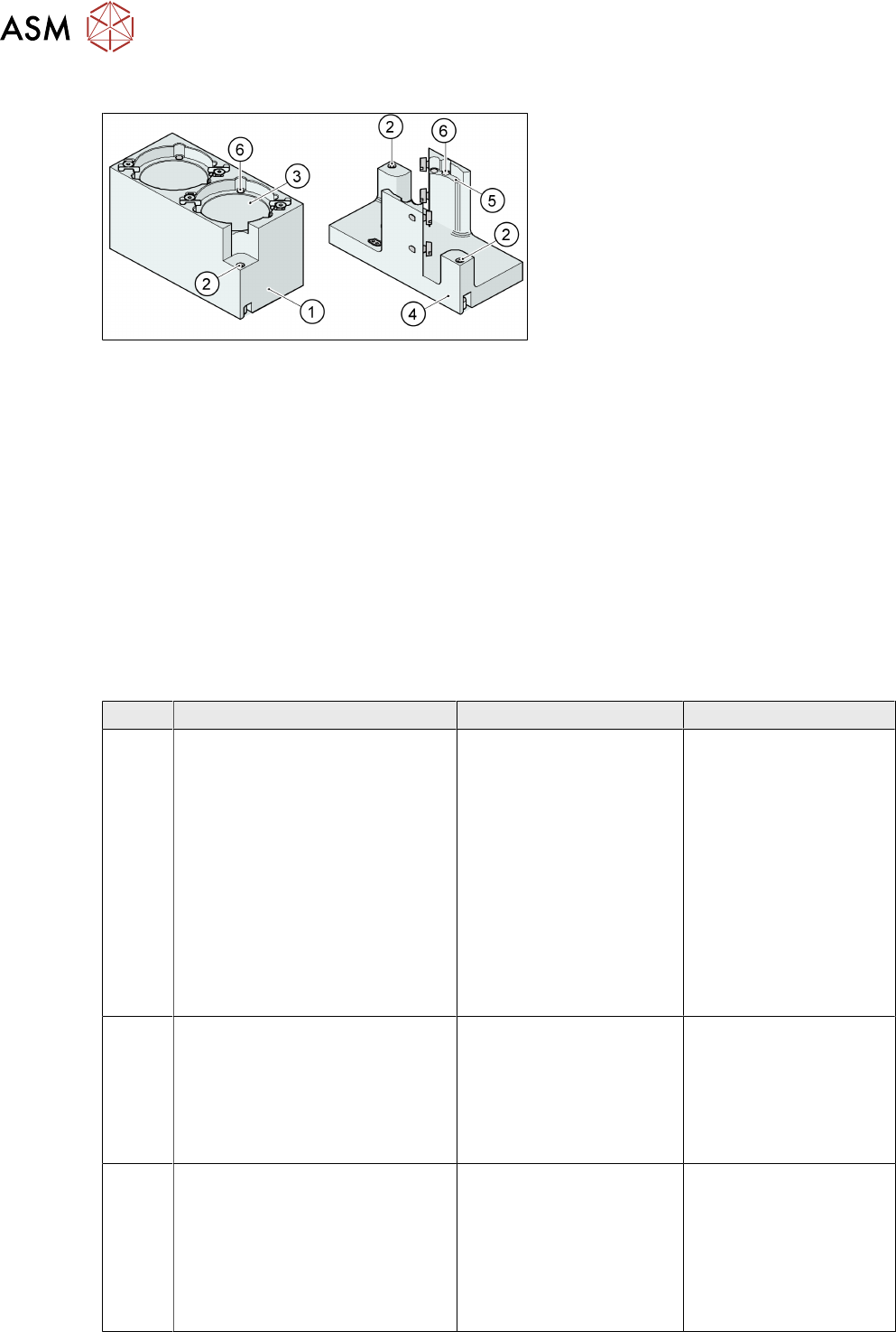
5.7.1 Nozzle Changer Twin Head
1. Standard magazine
2. Positioning fiducials
3. Nozzle garage
4. Magazine for special nozzles
5. Nozzle garage for special nozzles
6. Balls for lifting the nozzles
This nozzle changer can accommodate up to 8 nozzle magazines. There are two different
magazine
types available: standard magazines and magazines for special nozzles or grippers.
The magazine for standard nozzles has 1 positioning fiducial for position detection, while the
magazine for special nozzles/grippers has two positioning fiducials. The nozzles are fixed in the
holder. They are then either locked for return or released for pickup, depending on the direction of
rotation of the D Axis.
Standard configuration:
●
3 magazines with two nozzle garages each.
●
1 magazine with one nozzle garage.
5.8 Analysis - Common Error List
Code Error Description Possible Cause Action
35410
35411
35412
35413
●
Left cutter not retracted
●
Left cutter not extended
●
Right cutter not retracted
●
Right cutter not extended
●
Incorrect proximity
switch position
●
Defective proximity
switch
●
Defective valve
●
Short of compressed
air
●
Defective cylinder
●
Check & adjust the
position of proximity
switch
●
Replace the switch
if necessary
●
Check power &
functionality of the
valve
●
Check compressed
air supply
●
Replace defective
cylinder
34946
34874
31820
35005
●
Stepping of feeder is not
possible
●
Feeder: tape drive error
●
Component was not trans-
ported into the specified
position
●
Tape is jammed or
twisted
●
Tape drive is faulty
●
Toothed wheel is
jammed
●
Check tape feeder
●
Replace the tape
drive or the feeder
●
Check the toothed
wheel and remove
any components
35401 Tape obstructed in tape duct or
couldn’t be cut
●
Stick tape material
used
●
Incorrect position of
cutter blade
●
Worn cutter blade
●
Check tape sticki-
ness
●
Test different
component tape for
cutting
●
Replace cutter
blade if necessary