00198171-02_Technical_Training_FSE_TX-Series_EN.pdf - 第70页
6 Conveyor System 6.4 Overview Conveyor Electrical System 70 Technical Training FSE SIPLACE TX-Series 01/2018 6.4 Overview Conveyor Electrical System SIPLACE Shuttle The SIPLACE Shuttle extension has two configurations, …
6 Conveyor System
6.3 Conveyor Functionality
Technical Training FSE SIPLACE TX-Series 01/2018 69
6.3.4 PCB convoy mode
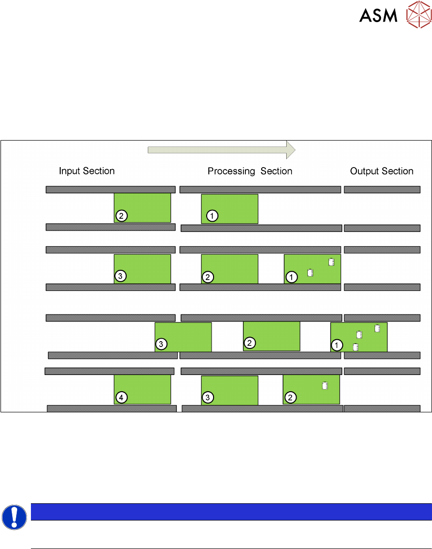
The TX is able to handle up to two PCBs in the placement area to reduce transport time.
Pre-condition:
●
Mode is enabled
●
PCB length is less than 175mm
●
Buffer zone light sensor is installed
A second PCB (PCB 2) is buffered in the processing area. Only PCB 1 will be processed and popu-
lated with components.
When PCB 1 leaves the processing area PCB 2 moves to the stopper and will be processed, at the
same time PCB 3 will move into the buffer zone in the processing area.
The Convoy mode is enabled by default but can be disabled under Service – Conveyor configura-
tion – Lane x – Parameters.
NOTICE
Vacuum tooling
PCB convoy mode is not possible when using vacuum tooling.
6 Conveyor System
6.4 Overview Conveyor Electrical System
70 Technical Training FSE SIPLACE TX-Series 01/2018
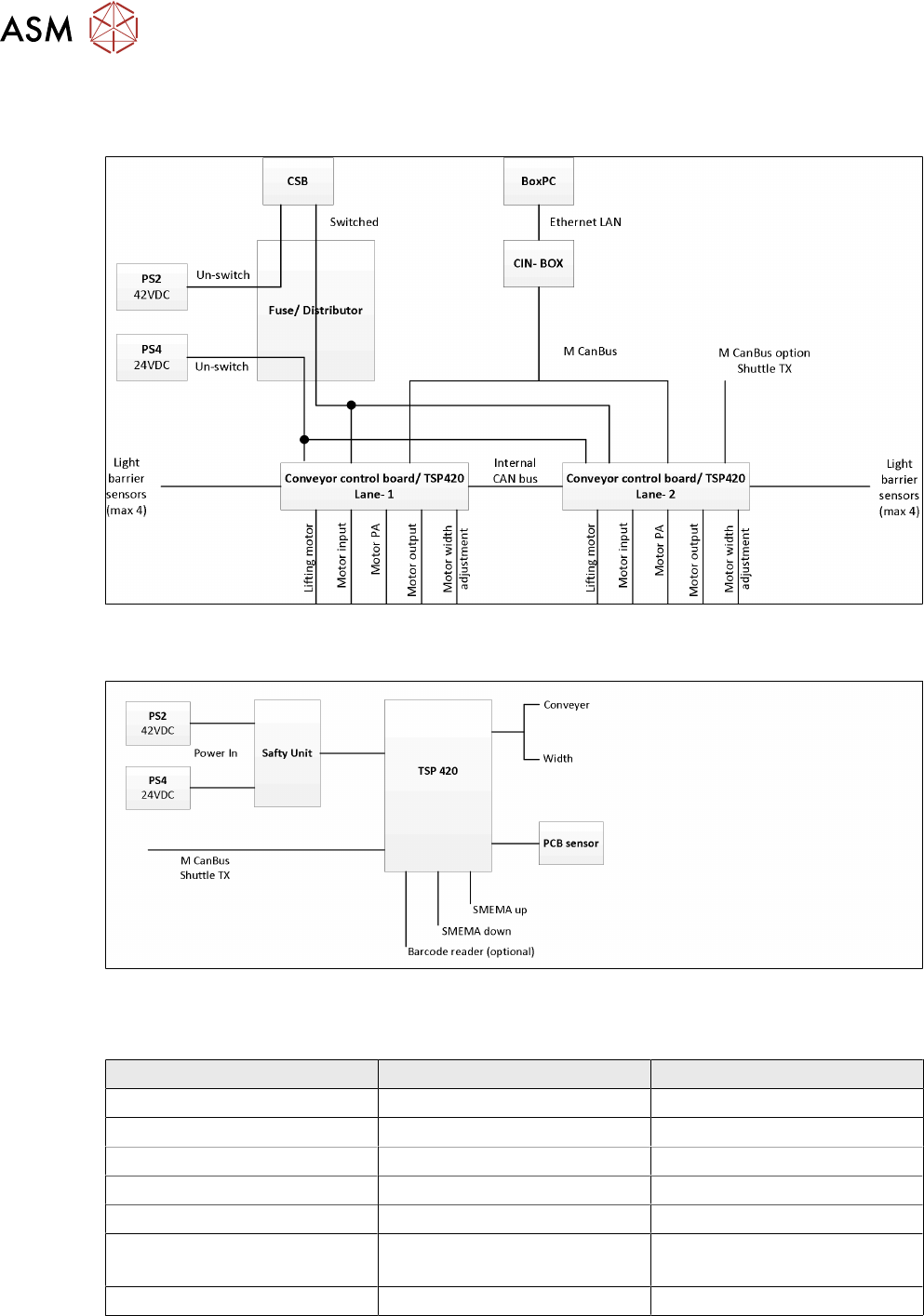
6.4 Overview Conveyor Electrical System
SIPLACE Shuttle
The SIPLACE Shuttle extension has two configurations, namely the upstream and downstream,
wiring connections and jumpers setting are stated below.
For more detailed information refer to the circuit diagram.
Upstream configurations Downstream configuration
Power connection to TX -X15.S1 -X15.S2
CAN bus connection to TX CAN3.EXT CAN3.EXT
Power connection to TX X50 X50
CAN bus connection to shuttle X52 X52
SMEMA connection to TX -XL1 and XL2 upstream -XL1 and XL2 downstream
SMEMA connection to shuttle -XL1-DS and XL2-DS (Down-
stream)
-XL1-US and XL2-US
(Upstream)
TSP 420 jumper setting JP1 pin 1 and 2 is shorted JP1 pin 1 and 2 is shorted
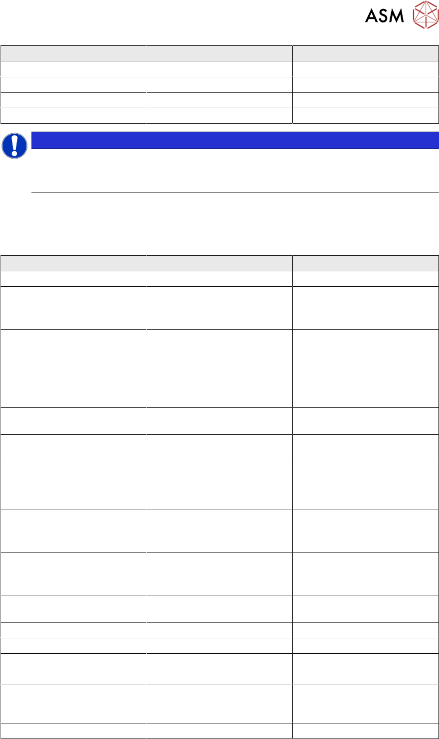
For special configurations where two SIPLACE Shuttle extensions are linked to a single SIPLACE
TXmachine, the CAN cable and TSP 420 jumper setting will be configured as per below.
6 Conveyor System
6.5 Parts Exchange / Settings / Calibration
Technical Training FSE SIPLACE TX-Series 01/2018 71
CAN cable IDC Connector Upstream configuration Downstream configuration
-X1 -X1*(cable: downstream) CAN3.EXT (TX)
-X1* No connection / spare -X1 (cable:upstream)
-X52 -X52 (shuttle upstream) -X52 (shuttle downstream)
TSP 420 jumper setting JP1 pin 1 and 2 is shorted JP1 pin 2 and 3 is shorted
NOTICE
Shuttle safety loop
The safety loop is not a hardware connected to the machine.
The safety loop is controlled by the machine software via CAN bus.
6.5 Parts Exchange / Settings / Calibration
6.5.1 Parts Exchange / Adjustment or Setting
Conveyor Parts Exchange Tools/ Setting Calibration
Lifting table plate Check motor current (lifting)
Lifting table motor
●
Calibrate motor
●
Check motor current (lift-
ing)
Conveyor drive* Belt tension device
●
Motor belt: 210Hz±20
●
Input: 49Hz±5
●
PA: 62Hz±5
●
Output: 170Hz±10
Check motor current (transport)
Toothed belt (conveyor belt)* Adjust belt tension in Input /
PA / Output, detail see above
Check motor current (transport)
Toothed belt (conveyor drive)* Belt tension device
Motor belt: 210Hz±20
Check motor current (transport)
Drive (width adjustment)* Belt tension device
●
Lane1: 25Hz±2
●
Lane2: 21Hz±2
●
Check motor current
(width)
●
Check width of conveyor
Toothed belt
(width adjustment)
Same with drive change,
see above
●
Check motor current
(width)
●
Check width of conveyor
Deflection pulley
(width adjustment)
Same with drive change,
see above
●
Check motor current
(width)
●
Check width of conveyor
Laser light barrier for the trans-
mitter / receiver
Adjust laser Calibrate transport fiducial
Fiber optic sensor Teach sensor in GUI
Fiber optic cable Teach sensor in GUI
Conveyor Control TSP420
●
Check Jumping Setting
●
Check/download firmware
X-fiducial bar ** Mechanical adjustment of the
PCB top edge to the transport
height
Calibration of the head offset
occurs automatically
Vacuum tooling *** ACT 15 µm tool Calibrate vacuum tool