00198171-02_Technical_Training_FSE_TX-Series_EN.pdf - 第87页
7 Power Supply 7.2 Wiring colour description Technical Training FSE SIPLACE TX-Series 01/2018 87 7.2 Wiring colour description There is wire colour code to show voltage level of specific single wires. So you can identify…
7 Power Supply
7.1 Overview of the Switched Mode Power Supply SMPS
86 Technical Training FSE SIPLACE TX-Series 01/2018
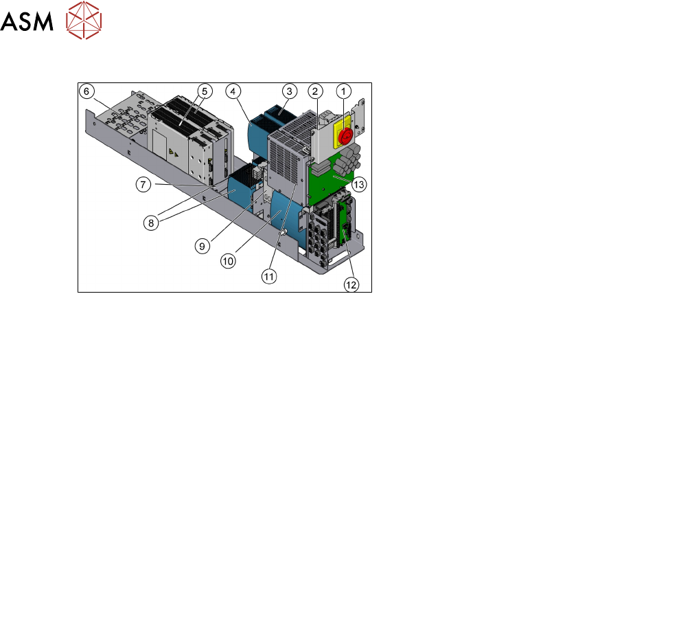
Overview SMPS
1. Main Machine Switch (separate panel from
SMPS)
2. PS5 (interior light also on separate panel)
3. PS3
4. PS4
5. MGCU 1&2
6. Cable harness interface
7. Link voltage testing point (300V)
8. PS1&2
9. CIN (Can Interface)
10. CAP1 (Capacitor battery)
11. CSB (Contact Safety Breaker)
12. I/O unit
13. FD (Low voltage fuse distribution)
Function Description
●
The switched mode power packs (multiple AC/DC converters) converts the line voltage to the
individual voltages needed.
●
No conventional power supply transformers are required.
●
Four power packs PS1, PS2, PS3 and PS4 are connected directly to the mains voltage 3 x
400VAC (exception low voltages countries).
The following voltages are generated:
PS1: 300VDC/160VDC
PS2: 42VDC
PS3: 28VDC
PS4: 24VDC
●
The high intermediate circuit voltages of the main axes (300VDC) and head axes (160VDC)
are backed up via the backup battery CAP and backup capacitors to the Fuse and Distribution
board FD assembly and on to the axis control assemblies. (MGCU and MHCU).
●
Voltage of 300VDC from PS1 used to charge capacitor battery in CAP assembly; this backup
battery emits energy to the main axes and also can absorb energy from the main axes.
●
The capacity of power pack PS1 is not enough for main axis acceleration (gantry jump) so en-
ergy is taken from the CAP, during gantry breaking the CAP is recharged, this function of the
backup battery removes the need for a ballast circuit.
7 Power Supply
7.2 Wiring colour description
Technical Training FSE SIPLACE TX-Series 01/2018 87
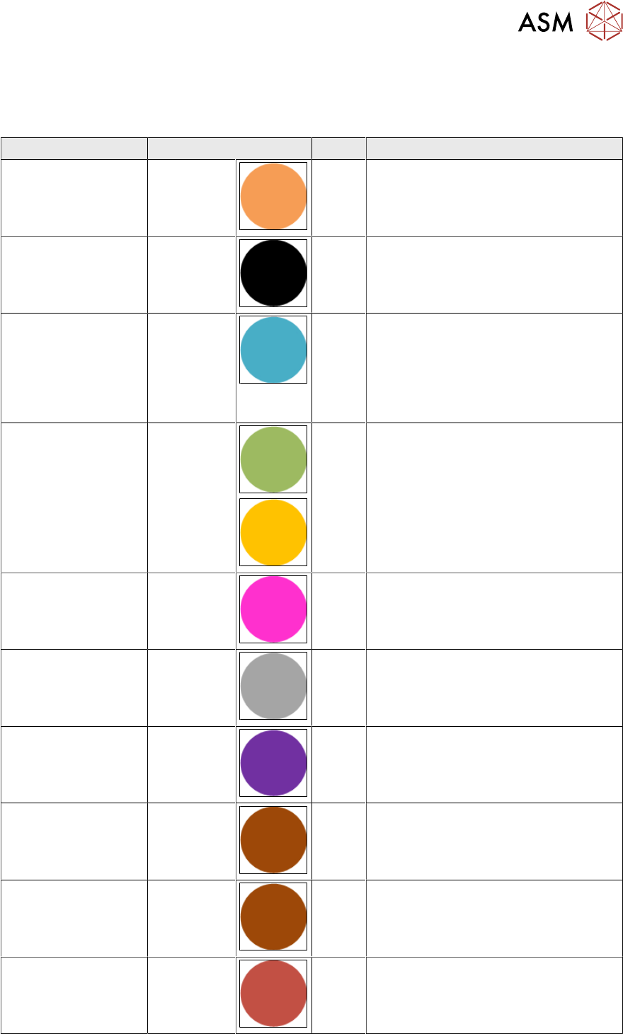
7.2 Wiring colour description
There is wire colour code to show voltage level of specific single wires. So you can identify voltage
levels at tested parts using wire colors:
Voltage Colour Code Comment
Mains Orange OR All circuits that will show voltage even if
main switch is OFF
Power general Black BK
Neutral line Light blue BU Europe:
According to EN and CE standards
wire color has to be light blue.
USA / Canada:
According to UL standards wire color
has to be white;
PE Green/Yel-
low
GNYE
DC 300 V Pink PK 300V DC link voltage
DC 160 V Grey GY 160V DC link voltage
DC 42 V Violet VT 42V DC link voltage conveyor and
head drives; vision flash voltage
DC 28 V Brown BN 28V FCU supply voltage
DC 24 V Brown BN
DC 24 V safety con-
trolled
Red RD
7 Power Supply
7.2 Wiring colour description
88 Technical Training FSE SIPLACE TX-Series 01/2018
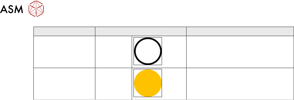
Voltage Colour Code Comment
GND, 0 V White WH
Control general Yellow YE Control, Inputs, Outputs, Emergency
stop