00198171-02_Technical_Training_FSE_TX-Series_EN.pdf - 第90页
7 Power Supply 7.3 Voltage Overview Block diagrams 90 Technical Training FSE SIPLACE TX-Series 01/2018 7.3.2 300 V Intermediate Circuit Voltage for Main Axes The following diagram illustrates the generation of the 300V i…
7 Power Supply
7.3 Voltage Overview Block diagrams
Technical Training FSE SIPLACE TX-Series 01/2018 89
7.3 Voltage Overview Block diagrams
7.3.1 Circuit Diagram of Power Supply TX
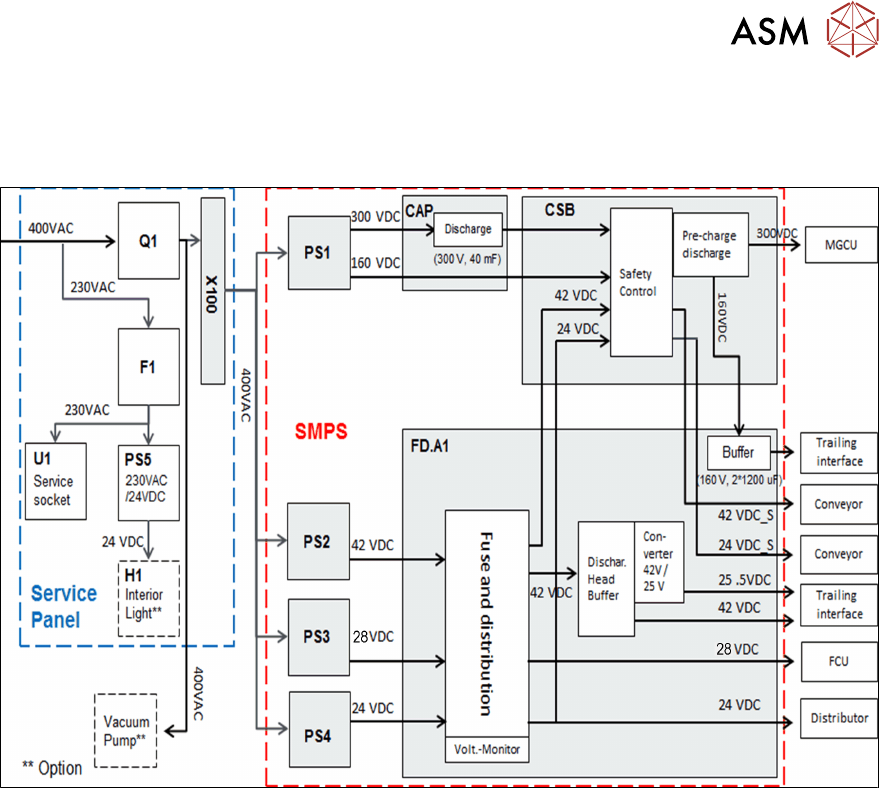
The diagram above shows a simple overview of the voltage generation with the SMPS.
●
The power pack PS1 converts the mains input AC voltage into 300VDC (for intermediate cir-
cuit voltage man axes) and 160VDC (for intermediate circuit voltage head axis).
●
The 300VDC is run via the backup battery CAP1 to the CSB (Contactor-based Safety
Breaker) the voltage is charged/discharged in a controlled manner via the pre/discharge board
A2 and the energy is backed up by the backup battery CAP1.
●
The power pack PS2 converts the mains input AC voltage into 42VDC.
●
One link of the 42VDC voltage is run via the CSB from where it is then run back to the FDB
and distributed as 42VDC_S (switched).The other link is directly to the discharge head buffer.
●
The power pack PS3 converts the mains input AC voltage into 28VDC.
●
The power pack PS4 converts the mains input AC voltage into 24VDC.
●
This 24VDC voltage is run via the CSB, from where it is then run back to the FDB and distrib-
uted as 24VDC_S (switched).
●
All voltages are protected by the Fuse & Distribution Board (FDB).
7 Power Supply
7.3 Voltage Overview Block diagrams
90 Technical Training FSE SIPLACE TX-Series 01/2018
7.3.2 300 V Intermediate Circuit Voltage for Main Axes
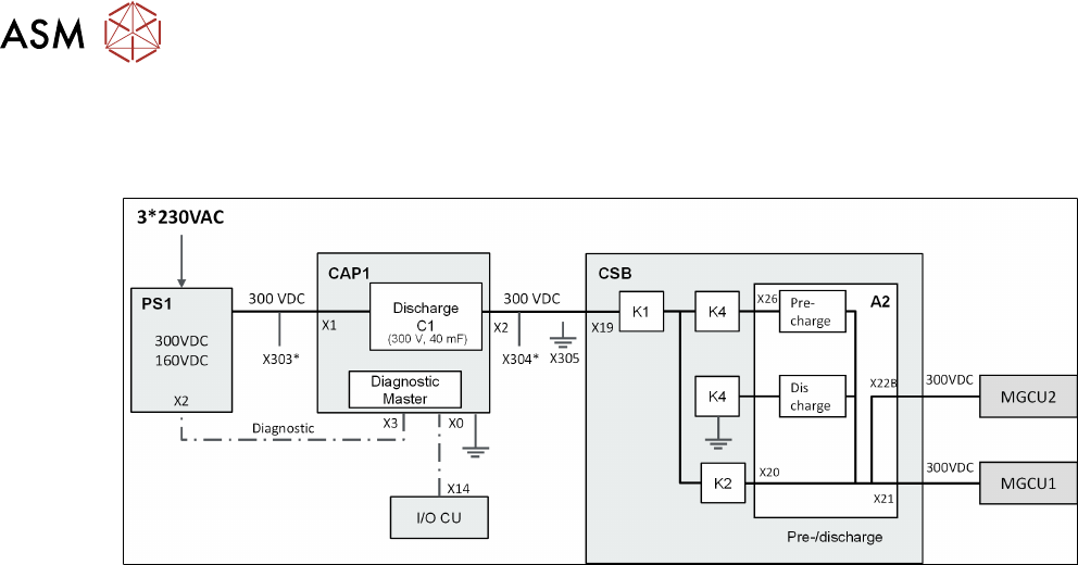
The following diagram illustrates the generation of the 300V intermediate circuit current for the
main axes.
* X303/X304 Service Testing point for DC 300V in/out
●
The 300VDC intermediate circuit voltage for the main axes is generated with the PS1 power
pack and is emitted directly via the CAP1 and the CSB assembly to the MGCU.
●
The capacitor battery CAP1 is charged with this 300VDC.
●
The control of pre-charging and discharging of the main axes in connection with the energy
management in the backup battery is managed by the pre/discharge board -A2 in the safety
breaker assembly (CSB).
7 Power Supply
7.3 Voltage Overview Block diagrams
Technical Training FSE SIPLACE TX-Series 01/2018 91
7.3.3 160 V Intermediate Circuit Voltage for Head Axes
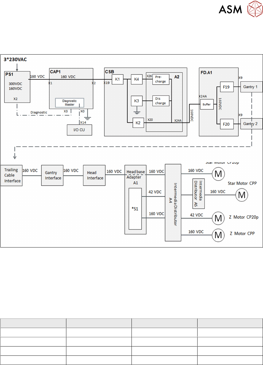
The following diagram illustrates the generation of the 160V intermediate circuit current for the
head axes.
*S1 Switch for Intermediate voltage Z Axis, 160V for CPP, 42V for C&P20 P
●
The 160VDC voltage (intermediate circuit) for head axis is not managed via the backup bat-
tery as no energy compensation problems occur here.
●
This voltage runs directly from the power pack PS1 via the backup battery CAP (without func-
tion) to the CSB and is switched there to the pre/discharge board.
●
The head axis voltage is then run via the FDB assembly, protected by fuses there and sent on
to the heads.
Voltage Type Fuse Usage
160 VDC Switched F19 Star Motor gantry 1
160 VDC Switched F19 Z Motor CPP gantry 1
160 VDC Switched F20 Star Motor gantry 2
160 VDC Switched F20 Z Motor CPP gantry 2