00198171-02_Technical_Training_FSE_TX-Series_EN.pdf - 第99页
7 Power Supply 7.6 Function Description of Individual Assemblies SMPS TX Technical Training FSE SIPLACE TX-Series 01/2018 99 7.6.2.1 Power Supply(SMPS) – Safety Indication Lamp indication on PS1 ● LED Green 300VDC to 220…
7 Power Supply
7.6 Function Description of Individual Assemblies SMPS TX
98 Technical Training FSE SIPLACE TX-Series 01/2018
7.6 Function Description of Individual Assemblies SMPS TX
7.6.1 Main switch
The main switch is combined with a motor protection switch with combined trip block.
It is approved as a mains breaker device, main switch and protective switch.
The trigger current for the protective switch does not need to be set, however depending on usage
there are 2 different types of motor switch.
●
Standard: Main circuit breaker 3~380-415V: 03125553-(6.3A)
●
Low voltage countries: Main circuit breaker: 3RV27 3 pole 03138992-(12,5A, UL489)
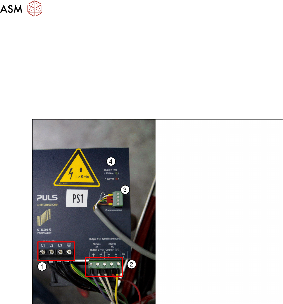
7.6.2 Power Pack PS1-(330 VDC/ 160 VDC)
1. Input Connection 3 phase AC
2. Output 300 VDC/ 160 VDC
3. Diagnosis connector
4. LED for displaying residual voltage
●
The 300VDC voltage is used for the main axis drives. Due to the high current peaks, this
voltage needs to be buffered at the output end.
●
The buffering of the 300VDC voltage is realized with the CAP1 backup battery.
●
A pre/discharge control function on the pre/discharge board A2 is used for controlled energy
release (during acceleration) and energy absorption (during braking) by the backup battery for
the main axes.
●
The 160VDC voltage is used for the head axes. Once again, the high current peaks require
backup storage at the output end.
●
The backup storage of the 160VDC voltage takes place on the pre/discharge board -A2 with
the help of capacitors.
7 Power Supply
7.6 Function Description of Individual Assemblies SMPS TX
Technical Training FSE SIPLACE TX-Series 01/2018 99
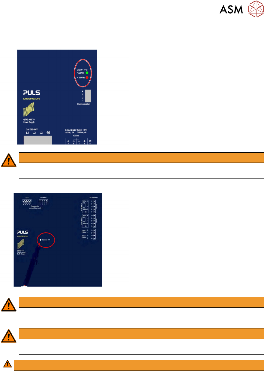
7.6.2.1 Power Supply(SMPS) – Safety Indication
Lamp indication on PS1
●
LED Green 300VDC to 220VDC
●
LED Red 220VDC to 5VDC
●
LEDS Off less than 5VDC
WARNING
Only after the voltage dropped <5VDC (both LED lamps off) can you work on the power
supply unit without hazard!
Lamp indication on CAP1
●
LED Red greater than 5VDC
●
LED Off less than 5VDC
WARNING
Only after the voltage dropped <5VDC (LED lamp off) can you work on the CAP1 unit
without hazard!
WARNING
The LED status do not grantee that the units are free from voltage it is always necessary to
measure the voltage before commencing service work.
WARNING!
.
7 Power Supply
7.6 Function Description of Individual Assemblies SMPS TX
100 Technical Training FSE SIPLACE TX-Series 01/2018
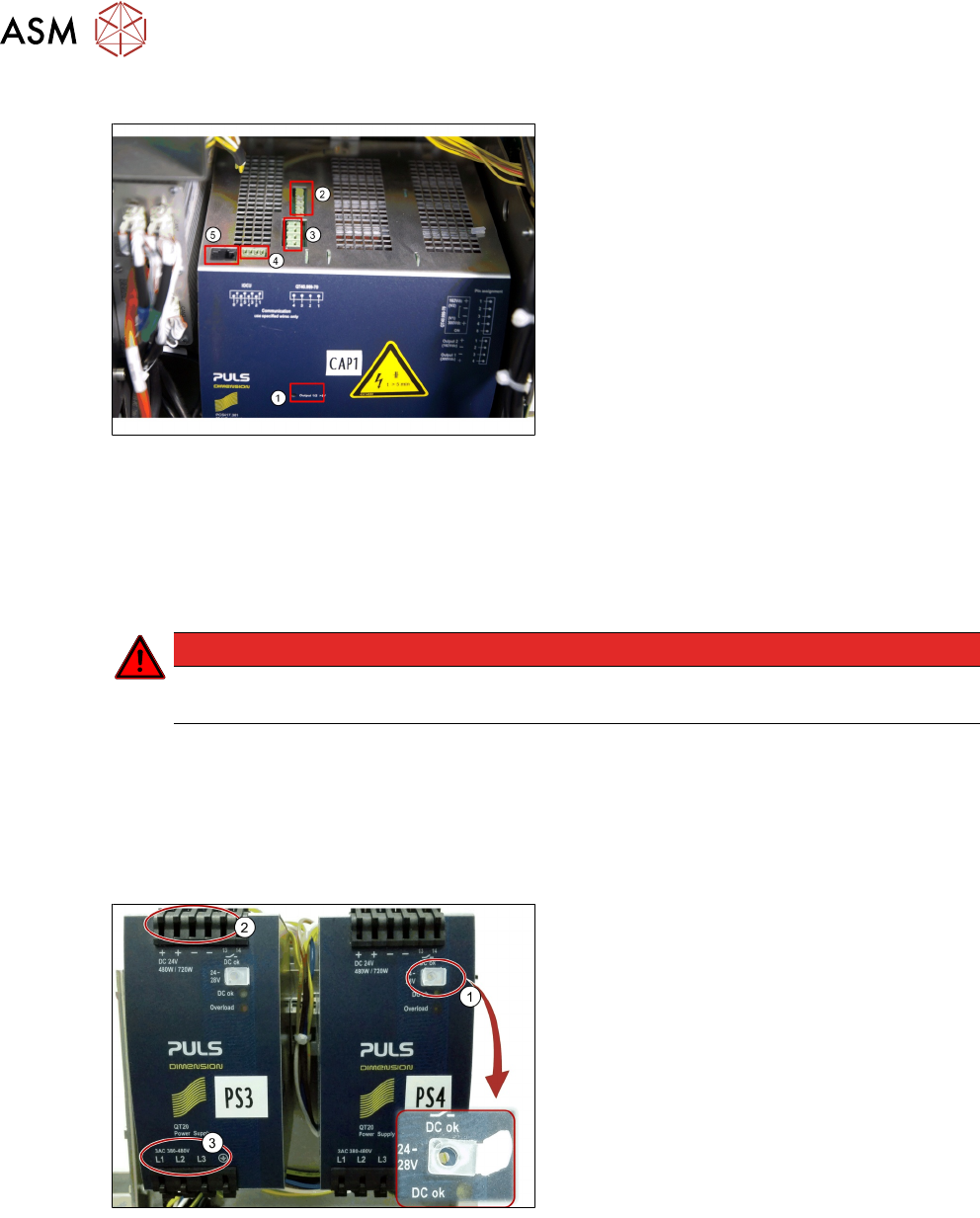
7.6.3 CAP1 - Capacitor Battery (Backup Capacitor)
1. Residual voltage LED (ON > 5V → Haz-
ard!)
2. Input DC IN 300V/160V from power pack
PS1
3. Output DC power out 300V/160V to CSP
4. Diagnostics cable (information diagnostic 1
from PS1)
5. Diagnostics cable LAN to distribution-
board
During braking of the main axes, the capacitor battery CAP1 is charged. This occurs as a result of
the excess energy (generative principle) during braking of the main axes.
●
In the state "emergency STOP" a connection (60ms) to the main axes remains, so that the
braking energy can be discharged.
●
This time delay is controlled by the CSB assembly.
●
In the event of an "emergency STOP/cover open" the capacitor battery will remain energized.
DANGER
The CAP1 assembly – capacitor battery may never be opened!
Risk of electrical shock with lethal voltages
Very important:
Please make sure that the CAP1 assembly is connected to the machine main ground point (MGP).
7.6.4 Power Pack PS2-PS3 and PS4
The power pack PS2/PS3/PS4 is supplied with a mains voltage of 3 x 400VAC (range
360V-440VAC) and provides between 24-42V DC.
1. The output voltage can be adjusted using
the potentiometer behind the white cover.
2. The output voltage can be measured at
terminal Plus+ and Minus-.
3. The input voltage can be measured using
the terminal L1/L2/L3.
The required output voltages are:
PS2 42VDC (+- 500mv)
PS3 28VDC (+- 200mv)
PS3 24VDC (+- 200mv)
Incorrect voltage settings may lead to machine malfunction. It is recommended to check the output
voltages after part exchange, also to avoid damage measure output before connecting output
cables.