F5 SERVICE MAUNAL.pdf - 第106页
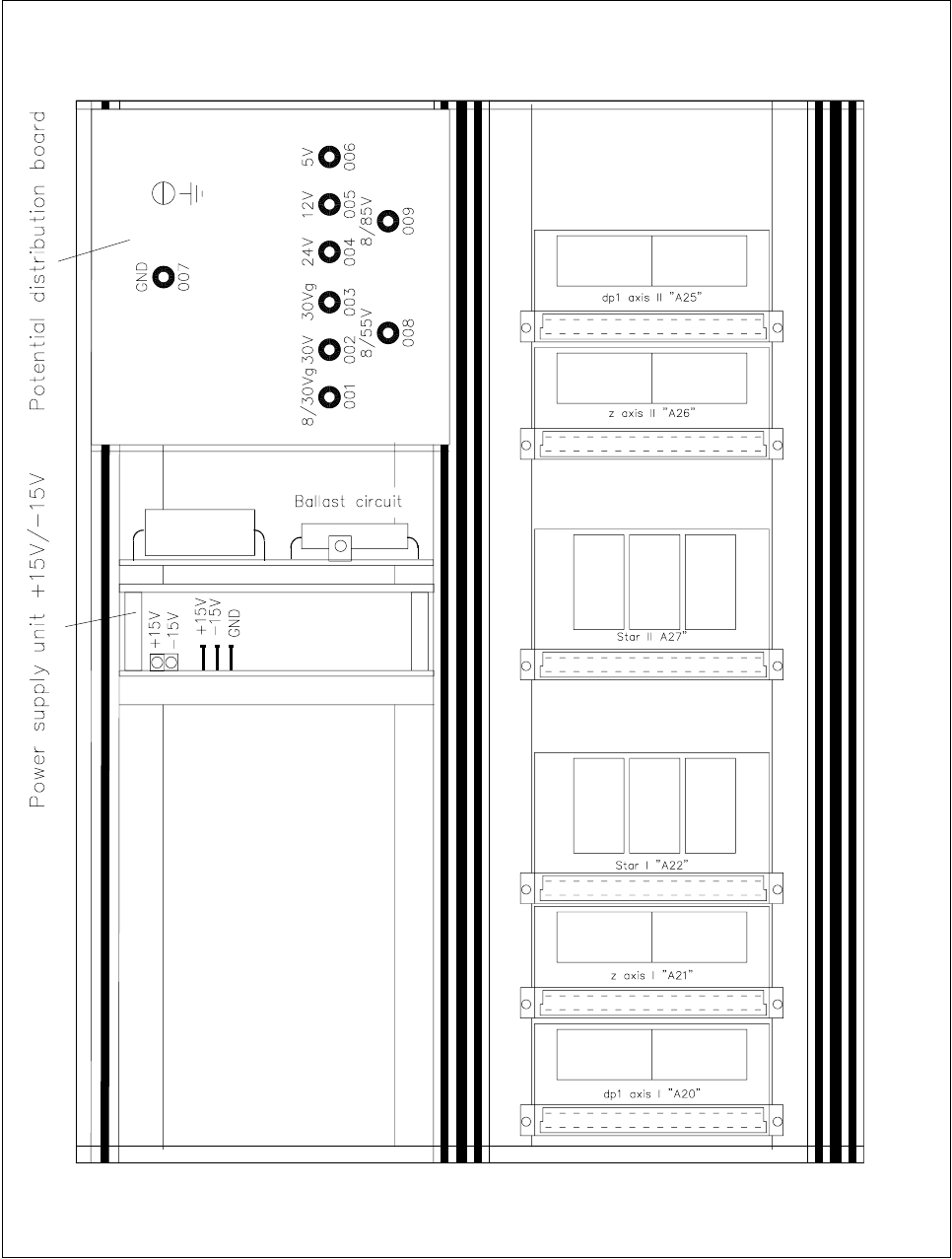
4 Power Supply SIPLACE 80S-20/F4 Service Manual 4.4 Servo Unit Edition 01/96 4 - 20 Fig. 4.4.1 Servo unit - partial view of the f ront, measuring points f or voltage

SIPLACE 80S-20/F4 Service Manual 4 Power Supply
Edition 01/96 4.4 Servo Unit
4 - 19
4.4 Servo Unit
4.4.1 General Comments
The servo unit is located on the right-hand side of the back of the SIPLACE machine in the machine base (see
Fig. 4.1.1).
● Open the metal door of the servo unit.
● In the top of the servo unit you will find the power pack for the 15 V supply voltage and the potential distrib-
utor (see Fig. 4.4.1).
● Switch the main switch of the machine on and press the Control on button.
NOTE
The Emergency stop button may not be pressed. All of the voltages must be found in the power supply unit
and all automatic circuit-breakers must be switched on (see Fig. 4.2.1).
● At the measurement points of the power pack you should measure voltages +15 V and -15 V against the
measuring point GND.
The LEDs will come on if the voltages are present (see Fig. 4.4.1).
● At the potential distributor you should measure at measuring point MP8 55 V against MP7 GND when
Control on has been pressed and 12 V after the Emergency stop button has been pressed.
● At the potential distributor you should measure the specified direct voltages at measuring points MP2,
MP4, MP5, MP6 against MP7 (GND).
NOTE
Voltages will be present at measuring points MP2, MP4, MP5 and MP6 even when the control unit is switched
off and the Emergency stop button has been pressed.
The voltages at measuring points MP1, MP2, MP3, MP8 and MP9 are not regulated. For this reason the volt-
ages as actually measured may be around 20 % higher than the rated voltage.
● At the potential distributor at measuring point MP3 you should measure 30 V against MP7 GND when you
have Control on and 0 V after pressing the Emergency stop button or a protective circuit-breaker.
● At the potential distributor at measuring point MP8 you should measure 55 V against MP7 GND when you
have Control on and 8 V after pressing the Emergency stop button or a protective circuit-breaker.
● At the potential distributor at measuring point MP9 you should measure 85 V against MP7 GND when you
have Control on and 8 V after pressing the Emergency stop button or a protective circuit-breaker.
4 Power Supply SIPLACE 80S-20/F4 Service Manual
4.4 Servo Unit Edition 01/96
4 - 20
Fig. 4.4.1 Servo unit - partial view of the front, measuring points for voltage

SIPLACE 80S-20/F4 Service Manual 4 Power Supply
Edition 01/96 4.4 Servo Unit
4 - 21
If you need to carry out any measurements at the back of the servo unit, proceed as follows:
● Switch the placement machine off and disconnect it from the power supply.
● Undo the servo unit retaining screw and pull the unit out.
CAUTION
Q
Make sure you do not damage the cable or put tensile stress on the snap-in connections.
● If necessary, support the servo unit with a stool.
NOTE
When making detailed measurements or carrying out fault location in the terminal rails or circuits you should
refer to the relevant circuit diagrams.