F5 SERVICE MAUNAL.pdf - 第115页
SIPLACE 80S -20/F4/F4-6/F5 Service Manual 5 Gantries Edition 09/99 5.1 Introduction 5 - 7 Fig. 5.1.2 General view of gantry from above: 80F 4 /F 4 -6/F 5 placement system

5 Gantries SIPLACE 80S-20/F4/F4-6/F5 Service Manual
5.1 Introduction Edition 09/99
5 - 6
5.1.4 Preparatory Work
We recommend that you always remove the components table before working on the gantry (see Section
12.1). This will make your servicing work much easier to perform.
5.1.4.1 Removing and Installing the Changeover Table
● Disconnect the changeover table’s electrical and pneumatic connections.
● Open the locking lever.
● With a lift truck lift the components table over the taper pins and move the changeover table out of the
machine.
● To re-install the changeover table proceed in the reverse sequence of operations.
Key to Fig. 5.1.1
.
Key to Fig. 5.1.2
.
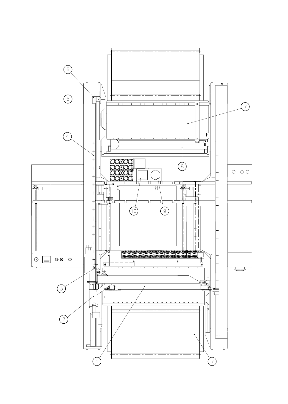
1 Y axis, gantry 2 2 Y-axis drive motor, gantry 2
3 X axis, gantry 1 4 X-axis drive motor, gantry 1
5 Y axis, gantry 1 6 Y-axis drive motor, gantry 1
7 X axis, gantry 2 8 X-axis drive motor, gantry 2
9 Used tape cutters 10 Components tables
11 Cover for conversion board 12
1 X axis 2 Cover for conversion board, large axis
3 X-axis drive motor 4 Y axis
5 Y-axis drive motor 6 Stop
7 Components tables 8 Used tape cutter
9 IC vision system 10 FC vision system
SIPLACE 80S-20/F4/F4-6/F5 Service Manual 5 Gantries
Edition 09/99 5.1 Introduction
5 - 7
Fig. 5.1.2 General view of gantry from above: 80F
4
/F
4
-6/F
5
placement system

5 Gantries SIPLACE 80S-20/F4/F4-6/F5 Service Manual
5.2 Replacing the Drive Motor of the X Axis Edition 09/99
5 - 8
5.2 Replacing the Drive Motor of the X Axis
5.2.1 Spare Parts, Auxiliary Materials and Equipment
– 1 motor for the x axis, complete, from item no. 00318553-01
– 2 cable ties
– Belt tension measuring device, from item no. 00326015-01
5.2.2 Removal
NOTE
You should comply with the safety instructions given in Section 1.
● Remove the cover for the conversion board, large axis.
● Unplug the flat ribbon cable and the motor cable from the conversion board, large axis.
● Remove the ribbon cable holder in a way that you can swing the entire cabling unit to one side.
● You will find it easier to get at the motor unit if you first remove the large axis conversion board, if neces-
sary.
● Unscrew and remove the hexagon socket screws which attach the motor to the flange.
● Tilt the motor a little to one side and carefully pull the toothed belt off the motor pinion.
● Pull the motor backwards and out of the flange.
NOTE
The motor is supplied as a complete unit consisting of the motor itself, the tachometer and motor pinion and
for this reason should also be replaced as a complete unit.