F5 SERVICE MAUNAL.pdf - 第128页
5 Gantries SIPLACE 80S-20/F4/F4-6/F5 Service Manual 5.5 Replacing the Drive Motor of the Y Axis Edition 09/99 5 - 20 5.5.3 Installati on ● Fit the new motor using the mounting screws . ● Restor e the mo tor ’s elect rica…
SIPLACE 80S-20/F4/F4-6/F5 Service Manual 5 Gantries
Edition 09/99 5.5 Replacing the Drive Motor of the Y Axis
5 - 19
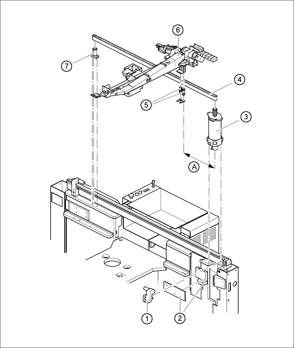
Fig. 5.5.1 Y-motor unit
5 Gantries SIPLACE 80S-20/F4/F4-6/F5 Service Manual
5.5 Replacing the Drive Motor of the Y Axis Edition 09/99
5 - 20
5.5.3 Installation
● Fit the new motor using the mounting screws.
● Restore the motor’s electrical connections (depending on the gantry)
NOTE
Route your cables with care.
● Tension the cut toothed belt as described in Table 5.5 - 1.
● Fit the components table support and the sliding plate holder.
● Replace the empty tape cutter and restore all electrical and pneumatic connections.
● Carry out a complete adjustment of the y axis (see adjustment instructions).
Key to Fig. 5.5.1
.
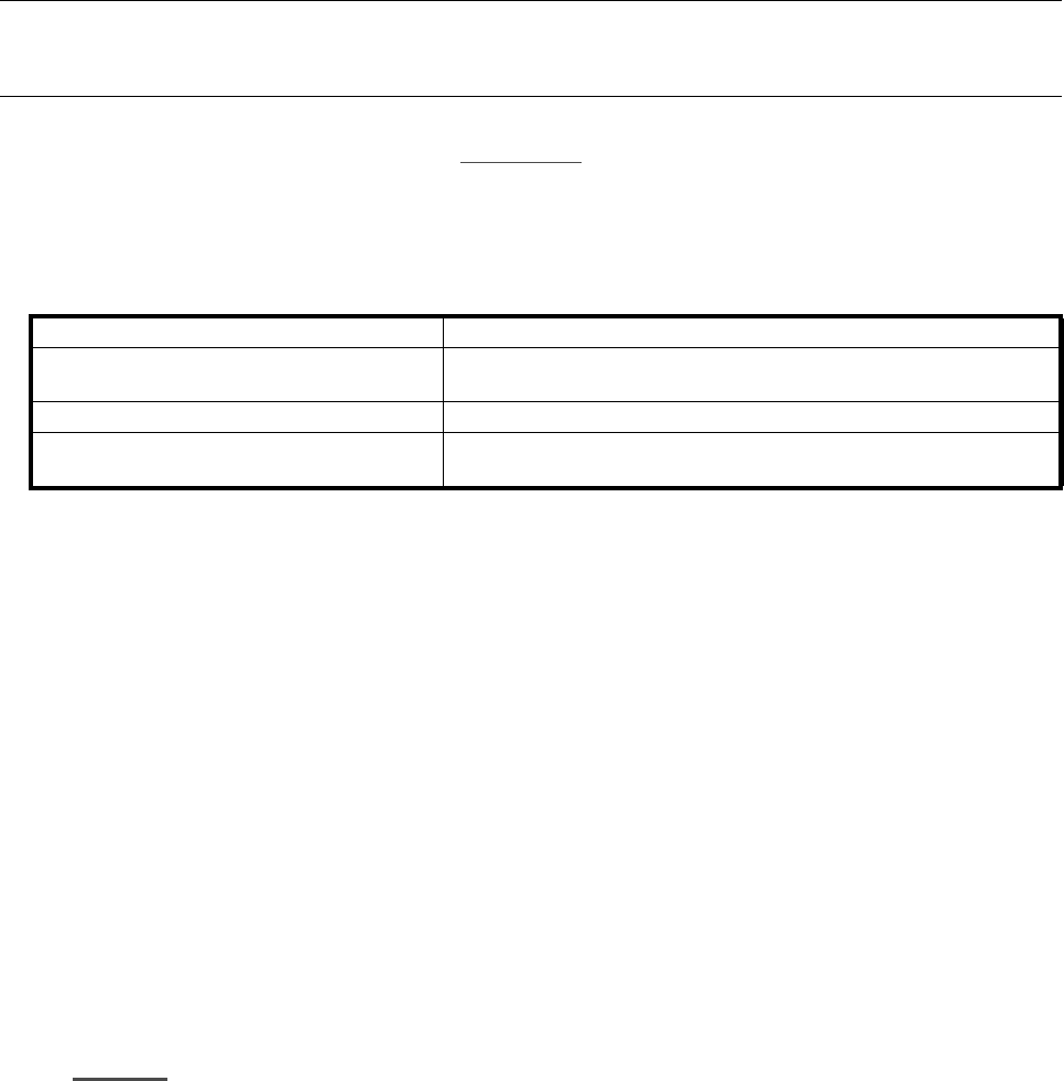
Length of the toothed belt 2540 mm
Measurement position on the toothed belt
600 mm from the center of the motor pinion to the center of the ten-
sioning roller on the motor side (see item A in Fig. 5.5.1)
Frequency of the new toothed belt 46 Hz ± 1 Hz
Frequency of the toothed belt once run in
(t
≥
5 hours
)
46 Hz ± 1 Hz
Table 5.5 - 1 Required adjustment of the cut toothed belt for the y axis
1 Stop (remove only in F
4
, F
4
-6 or
F
5
machines
2 Sliding plate and sliding plate holder
3 Y motor 4 Y-axis toothed belt
5 Tension rollers 6 X gantry
7 Y-axis deflection roller A Adjustment for the toothed belt tension: 600 mm distance
SIPLACE 80S-20/F4/F4-6/F5 Service Manual 5 Gantries
Edition 09/99 5.6 Replacing the Tension Roller for the Y-axis Toothed Belt
5 - 21
5.6 Replacing the Tension Roller for the Y-axis
Toothed Belt
5.6.1 Spare Parts, Auxiliary Materials and Equipment
– 1 tension roller, Y axis, from item no. 00321607-02
– Belt tension measuring device, from item no. 00326015-01
5.6.2 Removal
NOTE
You should comply with the safety instructions in Section 1.
● Loosen the Y-axis toothed belt on the tension rollers using a hexagon socket screw key, size 8
(see Fig. 5.5.1
).
● Loosen the three M6 hexagon socket screws which fit the tenion roller (see Fig. 5.5.1).
5.6.3 Installation
● Fit the new tension roller using the fastening screws.
● Tension the cut toothed belt in accordance with Table 5.5 - 1 on page 5 - 20.
● Carry out adjustment for the Y axis (see adjustment instructions).