F5 SERVICE MAUNAL.pdf - 第150页
5 Gantries SIPLACE 80S-20/F4/F4-6/F5 Service Manual 5.7 Exchanging the X -/Y-Trailing Cable Edition 09/99 5 - 42 5.7.7.3 Making the Correct Trailing Cable Transition from Y- to X-G antry Fig. 5.7.20 Transition from the Y…
SIPLACE 80S-20/F4/F4-6/F5 Service Manual 5 Gantries
Edition 09/99 5.7 Exchanging the X-/Y-Trailing Cable
5 - 41
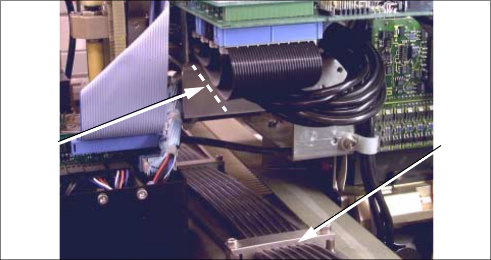
Fig. 5.7.19 Making the Plug-In Connections on the “Small Axis” board, Laying Ribbon Cable
● Pull the ribbon cables and the 7-tube hose down so that no large loops are left under the board in the head
area (see Fig. 5.7.19).
- Do not subject the hose and plug-in connections to any strain.
● Fasten the hose cable package in this position by tightening the counterstay.
● Run the X-trailing cable in the correct looping curve from the counterstay to X-gantry:
- The size of the imprint the 1st holdown made on the dismantled trailing cable may serve as an indica-
tor of the size of the loop.
- The 7-tube pneumatic hose must exactly follow the loop of the ribbon cable package.
- The loop of the X-trailing cable must be adjusted to the min. and max. travel position as shown in
Fig. 5.7.2 dargestellt. To adjust and check the position, move the placement head by hand.
- In the position 2 of the X-gantry shown in Fig. 5.7.2 he hose must fit closely against the ribbon cable
package but is not to exert pressure on it.
- In Pos. 1 there will be a small space between the ribbon cable package and the 7-tube pneumatic
hose because the end of the loop is shorter in this position.
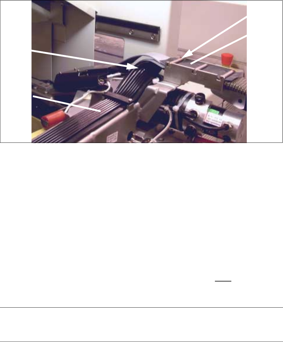
● Fasten the X-trailing cable (cable/hose package) in the position determined, using the 3 holddowns on
the X-axis (2 screws each, size 2.5 Allen wrench: see Fig. 5.7.2 and Fig. 5.7.19).
Holddown
Correct
laying for
cable
5 Gantries SIPLACE 80S-20/F4/F4-6/F5 Service Manual
5.7 Exchanging the X-/Y-Trailing Cable Edition 09/99
5 - 42
5.7.7.3 Making the Correct Trailing Cable Transition from Y- to X-Gantry
Fig. 5.7.20 Transition from the Y- to the X-Gantry: Making the Correct 90° bend in Cables and Hoses
● In the area of the bend, first carefully separate the pneumatic tubes into three pairs of 2 tubes each and
a single tube to create the flexibility necessary to shape the bend.
● Run the ribbon cable-package and the pneumatic line in a 90° bend from the Y- to the X-gantry, exactly
as shown in Fig. 5.7.20 dargestellt.
- The ribbon cable package at the bottom of the X-gantry area must be in the top of the Y-gantry area.
The 2 ribbon cables from the conversion board “Large Axis” are over them.
- The hoses must be touching the ribbon cable in the entire area.
- No kink and no bulging radius which is too small or too large are permitted.
● Run the two short ribbon cables from the top down to the Y-trailing cable.
The sequence of the cables depends on the designation on the conversion board “Large Axis”.
5.7.7.4 Y-Gantry Area: Installing New Protective Hose over the New Cable Set and
7-Tube Pneumatic Hose
CAUTION O
A pure polyester hose is always used on the machine option F5 DCA instead of the standard protective
hoses (see Section 5.7.2).
● Make certain that the ribbon cables are not twisted.
● Run all of the ribbon cable connectors on the bottom end of the cable (connection to gantry board) pre-
cisely against one another, as previously done during disassembly (see Fig. 5.7.7).
90° bend
Y-trailing
X-trailing
cable
Pin (3x)
cable

SIPLACE 80S-20/F4/F4-6/F5 Service Manual 5 Gantries
Edition 09/99 5.7 Exchanging the X-/Y-Trailing Cable
5 - 43
● Completely wrap the connect with Masking tape.
There are to be no remaining sharp edges which might damage the protective hose while the cable is
being inserted.
NOTE
When you re-install the old 7-tube hose, you have to wrap the individual ends of the tubes with Masking tape
as described in Section 5.7.7.1.
Always use a new protective hose (Item No.: see Section 5.7.2).
● Make certain that the protective hose is cut off at a smooth, right-angle at the top end. It is not to be
frayed. If an error is made, cut the protective hose properly with sharp scissors - outside of the machine.
-> During this process, cutt off as little as possible.
NOTE
No fabric fibers are to reach the machine.
● Carefully (!) push the cable/hose package, wrapped end first, into the new protective hose.
● Push the protective hose into the correct position relative to the Y-trailing cable hanger
(see Fig. 5.7.21).
5.7.7.5 Y-Gantry Area: Laying and Fastening the Y-Trailing Cable
CAUTION O
Make certain, that the cable supply chain ist mounted correct (= wide U-bracket must be at top, see Fig.
5.7.21 -> Check 1 !). Incorrect assembly causes demage during the placement sequence.
● If the cable supply chain was completely removed/exchanged, fasten the (new) cable supply chain in
the correct position with the top retaining bracket (wide) at the bottom of the Y-trailing cable hanger (two
M 4 screws, size 3 Allen wrench: see Fig. 5.7.1 and Fig. 5.7.21).
● Run the Y-trailing cable from the Y-trailing cable hanger to the Y-strain relief device:
● The cover band must be on the outside of the cable supply chain (see Fig. 5.7.21).
● Run the protective hose (with the cable/hose package) barely into the Y-trailing cable hanger. At the
top, the protective hose should only protrude about 0.5 cm past the first pin (next to the 90° bend in
the cable: see Fig. 5.7.20).
● In the area of the Y-trailing cable hangers place the single piece of ribbon cable previously dismantled
back on the protective hose and place the thin rubber sheet on it (see Fig. 5.7.11), such that these
parts project about 1 cm past the first pin. First fasten the trailing cable (y-axis) to its hanger with at
least one pin (see Fig. 5.7.11).
● Guide the protective hose in a loop along the cable supply chain and then on to the “Y-strain relief
device" next to the Y-gantry rail.
● Place the Y-trailing cable in the “Y-strain relief device" and insert the reversing pin.