F5 SERVICE MAUNAL.pdf - 第159页
SIPLACE 80S-20/F4 Service Manual 6 PCB Handling Edition 01/96 6.1 Introduction 6 - 3 6.1 Introduction 6.1.1 Safety I nstructions This se ction describe s servic ing wo rk on the board ha ndling un it and o n the lifti ng…
6 PCB Handling SIPLACE 80S-20/F4 Service Manual
Edition 01/96
6 - 2
SIPLACE 80S-20/F4 Service Manual 6 PCB Handling
Edition 01/96 6.1 Introduction
6 - 3
6.1 Introduction
6.1.1 Safety Instructions
This section describes servicing work on the board handling unit and on the lifting table. During all work on
these units you should comply with the safety instructions given in Chapter 1.
6.1.2 Tools, Auxiliary Materials and Equipment Required
For all of the servicing work which you carry out on the board handling unit or on the lifting table you will
require the auxiliary materials and equipment described in this section. Additional auxiliary materials and
equipment and spare parts will be listed separately in the corresponding sections.
● 1 set of screwdrivers
● 1 set of hexagon socket wrenches
● 1 pair of wire cutters, small
● 1 digital voltmeter (class 1.5)
● SIPLACE 80S-20/F
4
spare parts catalog
● SIPLACE 80S-20/F
4
circuit diagrams folder
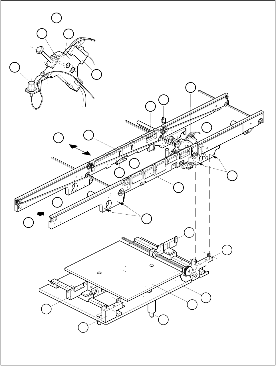
6.1.3 Overview of Functions
The printed circuit board transportation system taken as a whole consists of three units: the input, center and
output conveyors. The width of the board conveyor is continuously variable. You can specify the value for the
width of the conveyor board in the Single functions menu under the menu item Width adjustment. Depending
on your choice the stepping motor will change the width of the board conveyor at high or low speed. The
range of adjustment for the conveyor belt width lies between a minimum of 50 mm and a maximum of
460 mm. Limit switches interrupt the power supply to the setting motor when the permissible travel range val-
ues are exceeded.
Each conveyor unit has its own direct current motor to drive the conveyor belts. Sonar BEROS fitted to each
conveyor unit monitor the route of the board. The extendable stopper on the center conveyor stops the board.
The lifting table moves upwards and trips the rocking lever for the board clamping device. The board is then
clamped.
Before placement actually takes place, the board vision system determines the precise position of the board
and uses these positional values to calculate the placement co-ordinates of the components.
The circuit boards which control the belt motors and the lifting table motor are located inside the housing of
the board handling unit controller at the input end of the placement machine.
The servicing work described here applies not only to the SIPLACE 80S-20 but also to the 80F
4
machine
since these machines are equipped with the same board transport system.
6 PCB Handling SIPLACE 80S-20/F4 Service Manual
6.1 Introduction Edition 01/96
6 - 4
6.1.4 Position of the Assemblies (General Views)
Fig. 6.1.1 General diagram of board conveyor
D
4
10
9
3
2
1
5
A
5
6
F
B
E
C
8
7
G
11
12
15
14
13
11
12