F5 SERVICE MAUNAL.pdf - 第161页
SIPLACE 80S-20/F4 Service Manual 6 PCB Handling Edition 01/96 6.1 Introduction 6 - 5 Key to Fig. 6.1.1 Key to Fig. 6.1.2 A Direction of board transpor t B Direction of moveme nt of wid th adj ustment C Detailed view o f …
6 PCB Handling SIPLACE 80S-20/F4 Service Manual
6.1 Introduction Edition 01/96
6 - 4
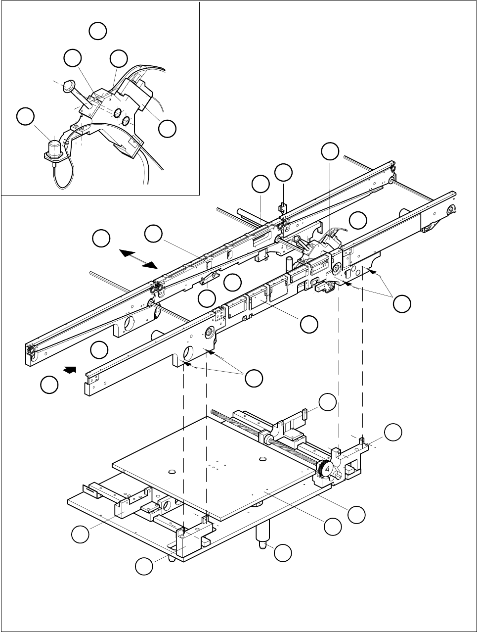
6.1.4 Position of the Assemblies (General Views)
Fig. 6.1.1 General diagram of board conveyor
D
4
10
9
3
2
1
5
A
5
6
F
B
E
C
8
7
G
11
12
15
14
13
11
12
SIPLACE 80S-20/F4 Service Manual 6 PCB Handling
Edition 01/96 6.1 Introduction
6 - 5
Key to Fig. 6.1.1
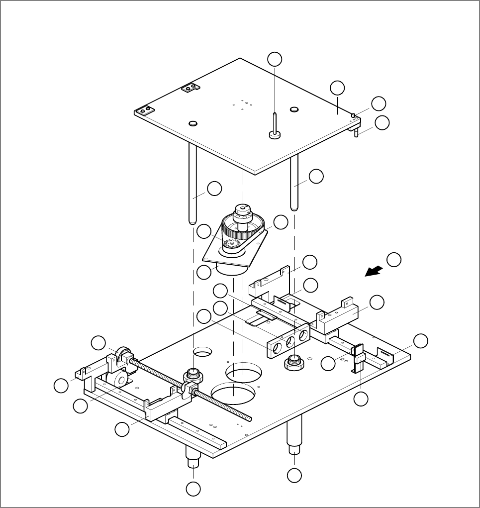
Key to Fig. 6.1.2
A Direction of board transport B Direction of movement of width adjustment
C Detailed view of board stopper D Board stopper basic module
E BERO F Sonar BERO
GValve
1 Input conveyor 2 Center conveyor
3 Output conveyor 4 Board stopper
5 Screws mounting the conveyor assemblies
onto the slide unit and onto the base unit
(in each case 2 M5 hexagon socket screws)
6 Conveyor side
7 Rocking lever 8 Movable side of conveyor
9 Guide rails for the board stopper 10 BERO for width adjustment
11 Slide unit (transportation support) 12 Base unit, fixed side, right (transportation support)
13 Mounting plate 14 Lifting table plate
15 Guide columns in the lifting table plate
1 Lifting table plate 2 Actuator for top microswitch
3 Actuator for bottom microswitch 4 Guide column
5 Synchroflex 16T5/455 toothed belt 6 Base, fixed side, righthand
7 Minimum board conveying width limit switch 8 Slide unit
9 Maximum board conveying width limit switch 10 Lifting table range limit switch, bottom
11 Lifting table range limit switch, top 12 Guide tube
13 Slide unit 14 Width adjustment stepping motor
15 Base, fixed side, righthand 16 Synchroflex 10T2.5/230 toothed belt
17 Mounting hole for sonar BERO evaluation
unit (output conveyor)
18 Mounting hole for sonar BERO evaluation unit
(input conveyor)
19 Mounting hole for sonar BERO evaluation
unit (center conveyor)
20 Lifting table motor
21 ALT5/Z16 synchronizing disk 22 Board support
A Direction of board transportation
6 PCB Handling SIPLACE 80S-20/F4 Service Manual
6.1 Introduction Edition 01/96
6 - 6
Fig. 6.1.2 Lifting table and width adjustment
1
12
3
4
6
7
5
8
9
10
12
13
14
15
16
17
18
19
20
21
22
4
A
2
11