F5 SERVICE MAUNAL.pdf - 第169页
SIPLACE 80S-20/F4 Service Manual 6 PCB Handling Edition 01/96 6.3 Drive Units of the PCB Transportation Systems 6 - 13 6.3 Drive Units of the PCB T ransp ortation Systems 6.3.1 Replacing the driv e unit of the i nput con…
6 PCB Handling SIPLACE 80S-20/F4 Service Manual
6.2 Geared Motors of the PCB Transportation Systems Edition 01/96
6 - 12

SIPLACE 80S-20/F4 Service Manual 6 PCB Handling
Edition 01/96 6.3 Drive Units of the PCB Transportation Systems
6 - 13
6.3 Drive Units of the PCB Transportation Systems
6.3.1 Replacing the drive unit of the input conveyor
Spare parts, auxiliary materials and equipment
Drive unit, transfer conveyor, fixed right-hand, Item No. 00324315-01 consisting of:
1 geared motor with synchronizing disk
1 motor mount
2 bearing bushes
1 synchronizing disk Al 8T2.5/25-0
1 synchronizing disk Al 13,5 T5/13-0
2 deep-grooved ball bearings 7 x 19 x 6 607-2Z
1 Synchroflex 6 T2.5/245 toothed belt
SITEST program
NOTE
The drive unit can only be replaced as a complete unit.
6.3.1.1 Removing the input or output conveyor drive units
NOTE OOO
It is essential that you also comply with the safety instructions given in Chapter 1.
● Select the maximum width setting for the board conveyor so that you can carry out servicing work unim-
peded.
● Move the gantry or gantries to outside the board transportation area.
● Switch off the machine at the main switch and disconnect it from the main power supply.
● Make sure that the machine cannot be switched on while you are carrying out servicing work.
● Undo and remove the two M3 hexagon socket screws of the sonar BERO mount (A).
● Carefully place the mount together with the sonar BERO on the machine base.
● Make sure that the connection cable does not get kinked or bent too tightly.
● Remove the cable shoes from the motor terminals.
● Strip from the motor the heat-shrinkable sleeves which fasten the connecting cable.
● Carry out the following work on the movable side of the board conveyor:
– On the inside unscrew and remove the two M 2 x 5 slotted head screws of the disk on the hexagonal
shaft (B).
– On the outside unscrew and remove the three M 3 x 5 hexagon socket screws in the flange (C).
● Undo and remove the two M4 hexagon socket screws which fasten the drive unit to the side part of the
fixed side of the board conveyor (D).
6 PCB Handling SIPLACE 80S-20/F4 Service Manual
6.3 Drive Units of the PCB Transportation Systems Edition 01/96
6 - 14
● Carefully slide the drive unit in the direction of the movable side of the board conveyor (E).
● Remove the flange and synchronizing disk from the hexagonal shaft.
● Lift the drive unit diagonally upwards and out (F).
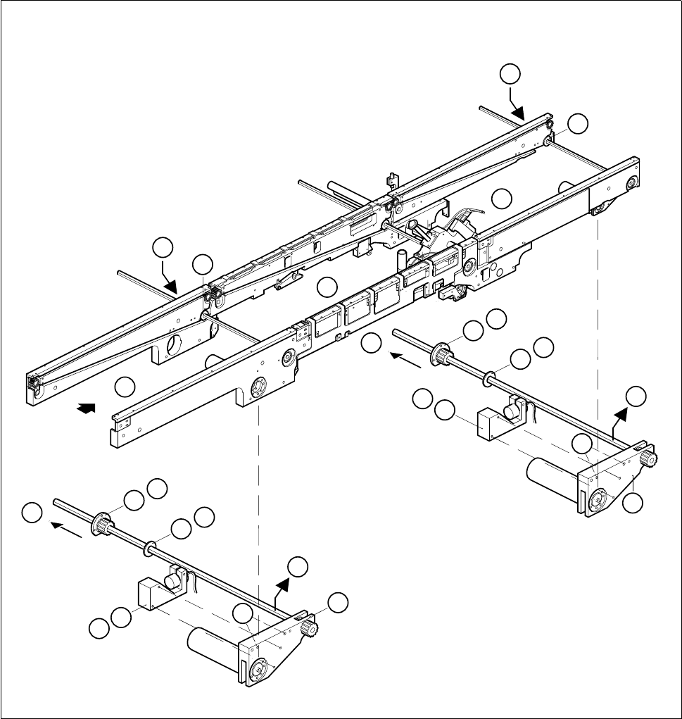
Fig. 6.3.1 Removing the drive unit of the input or output conveyors
Key to Fig. 6.3.1
1 Input conveyor 2 Center conveyor
3 Output conveyor 4 Sonar BERO mount of input / output conveyor
5 Drive unit of input / output conveyor 6 Center conveyor drive unit
7Disk 8Flange
3
1
2
5
7
8
8
7
4
E
8
7
A
B
C
D
F
4
E
8
7
A
B
C
D
5
F