F5 SERVICE MAUNAL.pdf - 第22页
1 Operational Safety SIPLACE 80S-20/F4/F4-6/F5 Ser vice Manual 1.1 Information on safety Edition 04/98 1 - 12 Every pr otectiv e cover on the aut omatic pl acement m achi ne has two recess ed grips (1). PLEASE NOTE Alway…
SIPLACE 80S-20/F4/F4-6/F5 Service Manual 1 Operational Safety
Edition 04/98 1.1 Information on safety
1 - 11
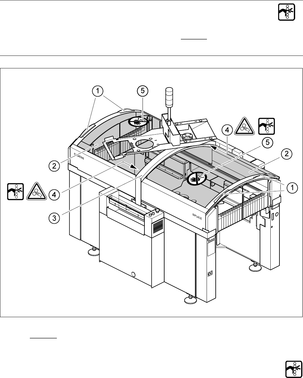
1.1.9 Safety instructions for opening the protective covers
To prevent any risk of injury when the protective covers on automatic placement machines are opened, the
owner must instruct his operators to use the protective covers exactly as specified in the following description.
RISK OF TRAPPING FINGERS IF THE PROTECTIVE
COVERS ARE OPENED OR CLOSED INCORRECTLY
m
When you open the protective covers, if you place one hand in one of the recessed grips (2) and place the
other hand on the protective cover in order to guide it (item (5) in Fig. 1.1.9
), you risk trapping your fingers in
the narrow gap (4) between the monitor traverse (3) and the protective cover (1).
Fig. 1.1.9 Protective covers on the SIPLACE automatic placement machine
.H\WR )LJ
1 Recessed grips for opening and closing the protective covers
2 Protective cover
3 Monitor traverse
4 Narrow gap (between 4 and 10 mm) between the monitor traverse and protective cover
m
5 Do NOT place your hand on this surface! e
1 Operational Safety SIPLACE 80S-20/F4/F4-6/F5 Service Manual
1.1 Information on safety Edition 04/98
1 - 12
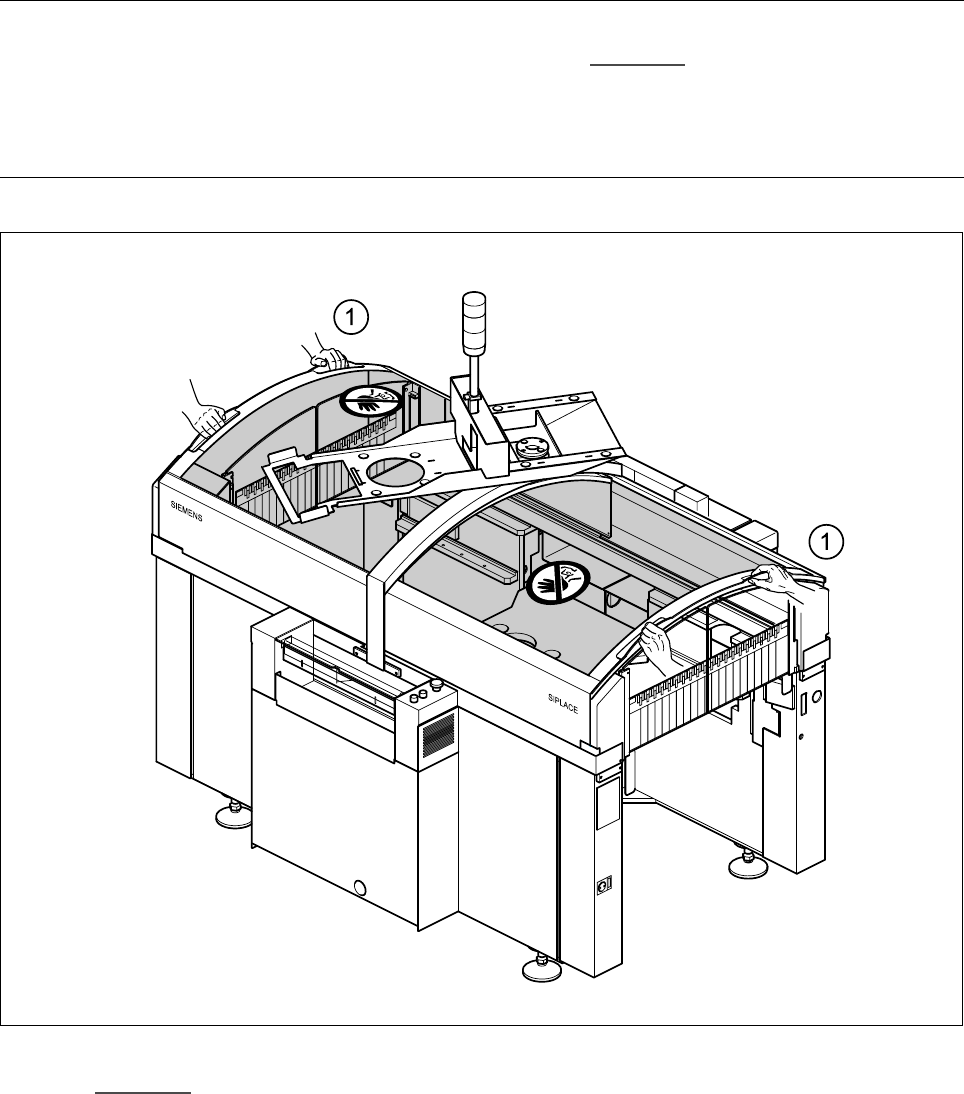
Every protective cover on the automatic placement machine has two recessed grips (1).
PLEASE NOTE
Always place both hands in these recessed grips (see point (1) in Fig. 1.1.10
) in order to open or close the
protective covers. This “two-handed operation” will prevent any risk of injuring your hands.
You will also avoid tilting the protective covers during opening or closing, which would place an excessive load
on the guides.
Fig. 1.1.10 Two-handed operation
.H\WR )LJ
1 Two-handed operation
SIPLACE 80S-20/F4/F4-6/F5 Service Manual 1 Operational Safety
Edition 04/98 1.2 Safety equipment
1 - 13
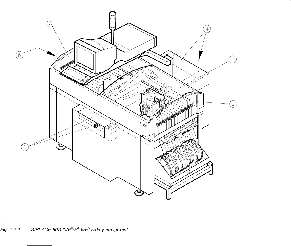
6DIHW\HTXLSPHQW
1.2.1 Protective covers
- Key to Fig. 1.2.1
1 Cover and guard on the input belt 2 Safety discs, righthand side
3 Protective cover 4 Cover and guard on the output belt
5 Protective cover 6 Safety discs, lefthand side