F5 SERVICE MAUNAL.pdf - 第238页
7 Components Table SIPLACE 80 S-20/F4 Service Manual 7.6 Empty Tape Cutting Unit and Empty Tape Channel Edition 03/97 7 - 36 ● Carry out a cuttin g test by (caution! danger of physic al injury from the blade!) a la rge e…

SIPLACE 80 S-20/F4 Service Manual 7 Components Table
Edition 03/97 7.6 Empty Tape Cutting Unit and Empty Tape Channel
7 - 35
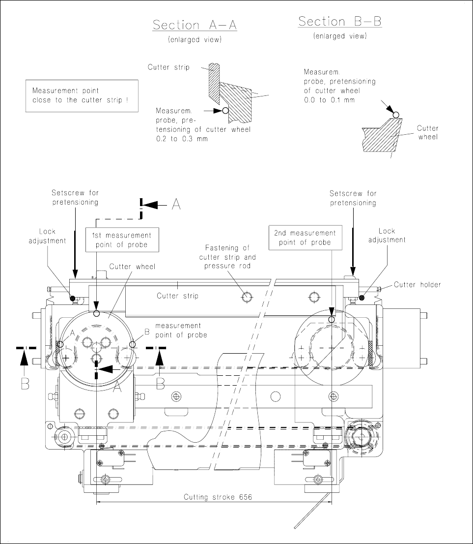
● Now move the cutter wheel so that point B is positioned below the measuring probe.
The measured value should lie anywhere between 0.0 ... 0.1 mm.
● Correct the adjustment at the slotted screw on the carriage (see Fig. 7.6.2).
7.6.8 Checking and Adjusting the Pretensioning of the Cutter Wheel
This check and adjustment should be carried out
– if the tapes are not being cut properly (pretensioning of the cutter wheel is too low),
– if stiffness has led to the motor switching out (pretensioning is too high),
– if you have replaced the cutter wheel and the cutter strip.
NOTE:
The empty tape cutting unit can remain installed for the following work on the machine. However in this case
you must remove the empty tape channel in order to allow access to the setting screws. Please note: after
reinstallation the empty tape channel has to be adjusted symmetrically to the pressure rod of the tape cutting
unit (see corresponding section, below).
CAUTION OO
Do not reach into the area of the cutter strip and cutter wheel: danger of physical injury!
● If the empty tape cutting unit has already been removed from the machine in the course of fault location,
set it down in a stable horizontal position, fastening it so that during the following work you can position the
magnetic holder with the measuring probe correctly on the guide rail.
● Move the cutter wheel carriage to the left-hand end position:
● Undo the locking of the left-hand and right-hand thrust pieces in the cutter holder and screw the thrust
pieces in until the cutter strip rests against the cutter wheel without pretensioning.
● Place the magnetic holder with measuring probe on the left on the guide rail and lower the measuring
probe onto the cutter wheel as shown in Fig. 7.6.2.
Please note:
The measurement point must be adjacent to the cutter strip, the display must now show "0.0 mm".
● Unscrew the thrust piece (left-hand) out of the cutter holder until the cutter wheel is pretensioned 0.2
to 0.3 mm by the cutter strip.
● Move the cutter wheel carriage by hand into the right-hand end position.
● Move the magnetic holder on the guide rail to the right.
● Place the measuring probe on the cutter wheel (see Fig. 7.6.2) and set it to "0".
● Screw out the right-hand thrust piece until the cutter wheel is pretensioned 0.2 to 0.3 mm.
● Check the setting by repeating the first measurement (= left-hand). If necessary, correct again the preten-
sioning of the cutter wheel and lock both thrust pieces in this position.
7 Components Table SIPLACE 80 S-20/F4 Service Manual
7.6 Empty Tape Cutting Unit and Empty Tape Channel Edition 03/97
7 - 36
● Carry out a cutting test by (caution! danger of physical injury from the blade!) a large enough piece of
foil of a suitable thickness (approx. 0.2 mm) to the cutter strip and moving the cutter wheel slide by hand.
After just one cutting stroke the foil must have been cut and separated.
Fig. 7.6.2 Checking and replacing the cutter strip and cutter wheel; adjusting the pretensioning

SIPLACE 80 S-20/F4 Service Manual 7 Components Table
Edition 03/97 7.6 Empty Tape Cutting Unit and Empty Tape Channel
7 - 37
7.6.9 D.C. Motor
7.6.9.1 Overview to Assist Further Fault Location:
Once the faults described above have been ruled out and the motor still will not activate, there may be
– a defect in the d.c. motors,
– a break in the components table interface cable Y559-W1 (plug X37 → communications unit),
– an interruption on the processor board of the communications unit.
● Since very little effort is required to install a replacement motor, by doing so you can quickly locate the fault
more precisely.
● Accordingly, if the new motor will not activate, first exclude a break in the "Components table interface"
cable Y559-W1.
● Next, and for test purposes, swap over the components changeover tables. In this way you can determine
whether the fault is ultimately caused by the communications unit (including cable Y559-W1).
● Proceed in detail as described below.
7.6.9.2 Replacement of the Motor Unit
● The components changeover table has already been removed from the machine in the course of fault
location.
● To be able to access the nut of the guide pulley on cutting unit, item no. 00313882, undo the screws secur-
ing the swivel cylinder.
● Undo the nut securing the guide pulley of the
● endless toothed belt.
● Remove the endless toothed belt.
● Disconnect all electric cables from the motor unit.
● Undo the four screws at the motor unit.
● Remove the motor unit.
● Install new motor unit and secure it using screws.
● Connect the electric cables to the motor unit.
● Place the cut toothed belt around the guide pulley and the motor unit.
● Attach the clamping connector so that the ends of the cut toothed belt are joined and clamped centrally.
● Move the cutter wheel to the park position.
● Tension the belt by displacing the guide pulley in the elongated hole.
● Measure the belt tension in the center of the endless toothed belt (Setpoint value: 30 - max. 35Hz).
NOTE:
Repeat the two aforementioned procedures until the belt is tensioned correctly.
● Fasten the swivel cylinder.
● Screw the motor onto the support (4 fillister head screws M3).