F5 SERVICE MAUNAL.pdf - 第273页
SIPLACE 80S-20/F4 Service Manual 8 IC Head Edition 01/97 8.3 Servicing Work on the Z Axis 8 - 11 5HS ODFHWK H(QG 3RVLWLR Q%(52 See ite m 6 in Fig. 8.3.1 page 8 - 12 ● Loosen the cl amping s crew for fi xing the…

8 IC Head SIPLACE 80S-20/F4 Service Manual
8.3 Servicing Work on the Z Axis Edition 01/97
8 - 10
5HSODFH0RWRU:LWK=$[LV7DFKR
7RGLVDVVHPEOH
● Slacken off the toothed belt as described in section 8.3.3, page 8 - 9 and pull it away.
● Detach all electrical cables to and from the motor.
● Loosen the hexagon socket head screw holding the motor in place.
● Remove the motor.
7RUHDVVHPEOH
● Position the new motor so that the end face of the motor ends flush with the head housing.
● Fix the motor in place with the hexagon socket head screw.
● Replace all electrical cables to and from the motor.
● Attach the driving toothed belt.
● Tighten the toothed belt as described in section 8.3.3, page 8 - 9.
● Check the zero point correction value and the axis servo setting (see section 8.3.9, page 8 - 14).
5HSODFH1R]]OH6XSSRUW6SULQJ6WHHO6KHHWRQWKH6OHHYH
See item 2, Fig. 8.3.1 page 8 - 12
PLEASE NOTE
If the spring plate of the sleeve mount is broken, the entire mount must be replaced.
● Fix the mount for the sleeve removal to the lower end of the sleeve.
● Unscrew the star.
● Lift the damaged spring steel sheet away from the star and fit the new plate. The alignment is determined
by the centering pin. The three beads in the spring steel sheet should point downwards.
● Remove any residues of glue from the thread.
● Apply a little LOCTITE 241 adhesive to the thread.
● Firmly bolt the star to the new spring steel sheet.
WARNING
Do not move the z axis unless the clamping device has been deactivated, since this could damage the
sleeve clamping device.
● Check the zero point correction of the d axis.

SIPLACE 80S-20/F4 Service Manual 8 IC Head
Edition 01/97 8.3 Servicing Work on the Z Axis
8 - 11
5HSODFHWKH(QG3RVLWLRQ%(52
See item 6 in Fig. 8.3.1 page 8 - 12
● Loosen the clamping screw for fixing the BERO.
● Replace the BERO.
● Position the BERO so that its end face is flush with the housing.
● Fix the BERO in place.
● Check that the BERO switches correctly.
$GMXVW$QWL5RWDWLRQ/RFNRQ%HDULQJ+RXVLQJ
See item 10 in Fig. 8.3.2 page 8 - 15
Two horizontal slots have been milled into the anti-rotation lock for adjustment purposes.
$GMXVWWKHDQWLURWDWLRQORFN
● Deactivate the z axis clamping device and push the sleeve up so that the bearing housing covers the end
face of the end position BERO (item 6, Fig. 8.3.1 page 8 - 12).
● Turn the bearing housing (item 11, Fig. 8.3.2 page 8 - 15) counterclockwise - viewed from above - towards
the mount (item 8, Fig. 8.3.1 page 8 - 12). This will activate the BERO.
● Now turn the bearing housing and the anti-rotation lock (items 10 and 11, Fig. 8.3.2 page 8 - 15) clockwise
towards the mount. The BERO should not be deactivated.
● If this is not the case, loosen the two M2 screws on the anti-rotation lock and push the lock towards the
mount. Tighten the two screws.
PLEASE NOTE
The gap between the anti-rotation lock and the mount should be between 0.5 mm and 1 mm.
● Check that the BERO switches correctly by moving the sleeve up and down several times. To do this,
loosen the z axis clamping device.
● Deactivate the clamping device and move the sleeve up and down. The end position BERO (item 6, Fig.
8.3.1 page 8 - 12) must switch.
8 IC Head SIPLACE 80S-20/F4 Service Manual
8.3 Servicing Work on the Z Axis Edition 01/97
8 - 12
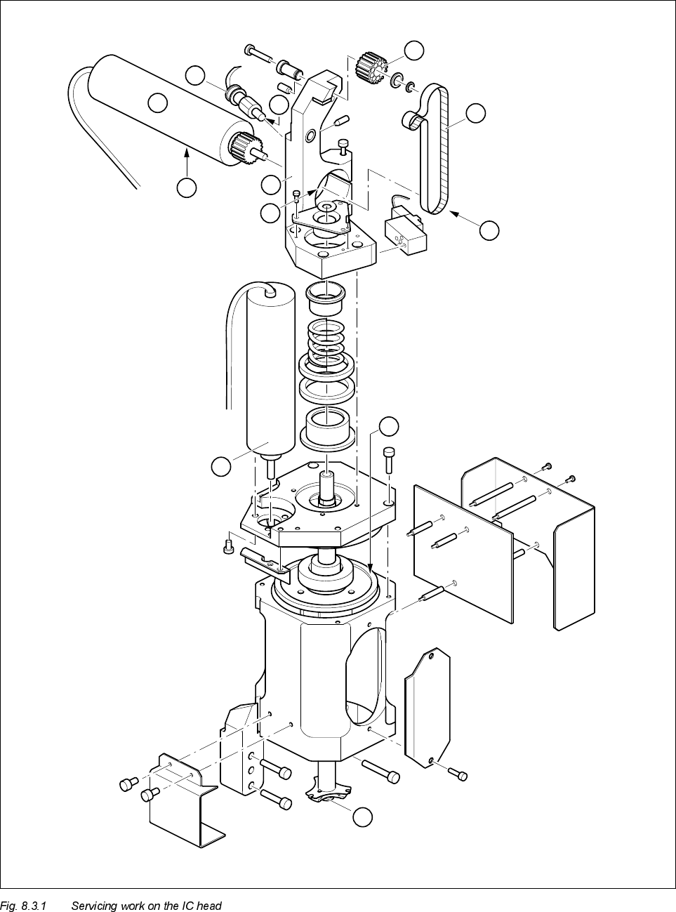
2
4
3
A
B
C
5
1
6
D
8
7