F5 SERVICE MAUNAL.pdf - 第303页
SIPLACE 80S-20/F4 Service Manual 9 12-Segment Revolver Head (10000) Edition 07/97 9.1 12-Segment Revolver Head (10000) 9 - 7 9.1.6 Removing the ’Placement Head Complete’ Spare pa rts Revolv er head 1 0000, fro m item no.…
9 12-Segment Revolver Head (10000) SIPLACE 80S-20/F4 Service Manual
9.1 12-Segment Revolver Head (10000) Edition 07/97
9 - 6
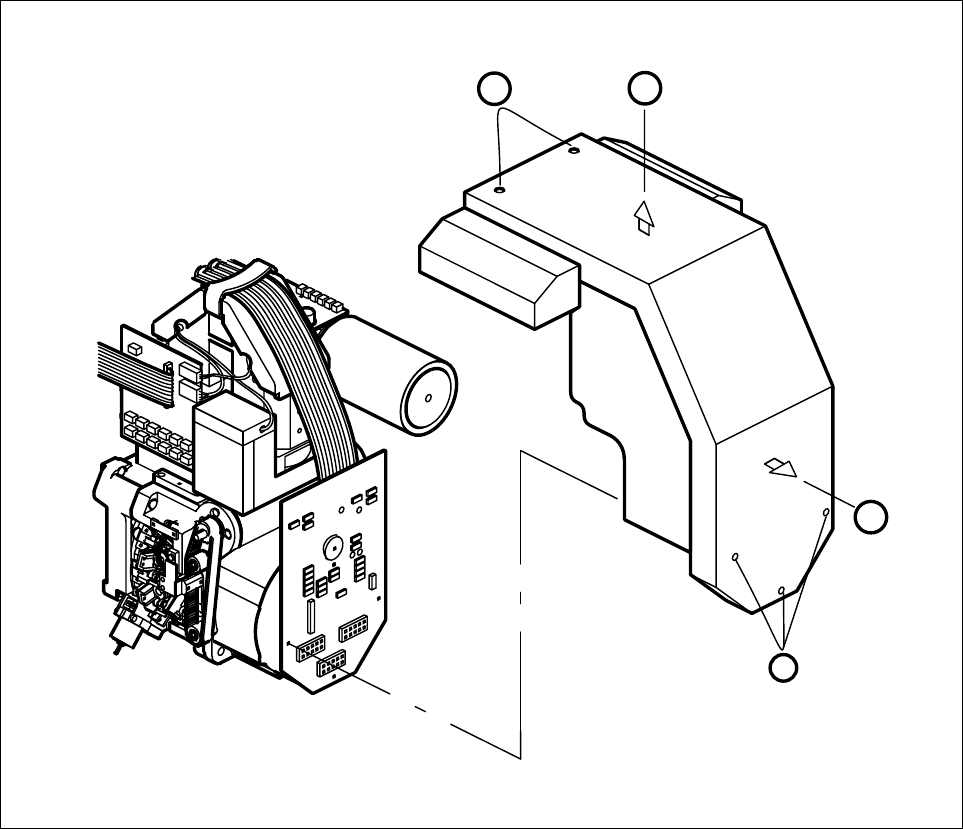
9.1.5 Removing the ’Cover complete’
● Remove the five M3x5 hexagon socket screws for mounting the cover (point A).
● Pull the cover a little towards you in horizontal direction (point B).
● Lift the cover up and away (point C).
● To install the cover, proceed in the reverse sequence of operations.
Fig. 9.1.2 Mounting and dismantling the cover
C
A
B
A
SIPLACE 80S-20/F4 Service Manual 9 12-Segment Revolver Head (10000)
Edition 07/97 9.1 12-Segment Revolver Head (10000)
9 - 7
9.1.6 Removing the ’Placement Head Complete’
Spare parts
Revolver head 10000, from item no. 00321406S01
● Disconnect plug-in connections X3, X10, X12, X13, X14, X17, X18 and X19 from head board C0005.
● Disconnect all compressed air lines from the back of the vacuum generator.
● Undo the three hexagon socket screws (M4 x 16) (Refer to section 9.1.3 A) and carefully remove the
placement head from the placement machine.
– To install the head, proceed in the reverse sequence of operations.
NOTE
Pay attention to the keying of the plug when you reconnect the plug-in connections to head board C0005.
CAUTION ∆
!
Make sure you do not damage the cable or put tensile stress on the snap-in connections.
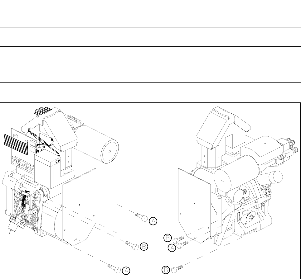
Fig. 9.1.3 Fastening screws of the 10000 placement head and the front part of the placement head
Key to Fig. 9.1.3
A Fastening screws of the placement head, complete
B Fastening screws for the front part of the placement head

9 12-Segment Revolver Head (10000) SIPLACE 80S-20/F4 Service Manual
9.1 12-Segment Revolver Head (10000) Edition 07/97
9 - 8
9.1.7 Removing the Front Part of the Placement Head
● Disconnect plug-in connections X3, X10, X12, X13 and X14 from head board C0005.
● Disconnect the compressed air line for the forced air unit from the front of the vacuum generator.
● Undo the three hexagon socket screws (M4 x 16) (Refer to section 9.1.3 B) and remove the front part of
the placement head from the placement machine.
● To re-install the front part of the head, proceed in the reverse sequence of operations.
● For information on the components camera adjustment procedure, please refer to the Sitest instructions.
NOTE
When you remove or re-install the front part of the placement head note that the star is rotated by 15° out of its
zero position (vertical sleeve position).
When you fit the front part of the placement head, make sure that the distributor disc (see Pos. 3, Fig. 9.4.2,
Page 9 - 19) is positioned correctly.