F5 SERVICE MAUNAL.pdf - 第307页
SIPLACE 80S-20/F4 Service Manual 9 12-Segment Revolver Head (10000) Edition 07/97 9.2 Replacing the Valve Adjustment Drive for the Placem ent or Reject Circuits 9 - 11 NOTE When fi tting th e head, pay attent ion to t he…
9 12-Segment Revolver Head (10000) SIPLACE 80S-20/F4 Service Manual
9.2 Replacing the Valve Adjustment Drive for the Placement or Reject Circuits Edition 07/97
9 - 10
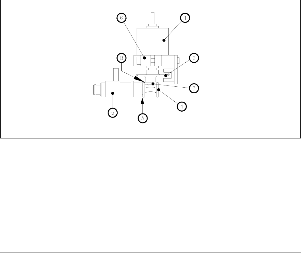
Fig. 9.2.1 Adjustment work on the valve adjustment unit
Key to Fig. 9.2.1
1 Step motor
2 Adjustment disc
3 Deep-groove ball bearing
4 Plunger
5 Valve housing
6 Adjustment unit
A Adjust distance between plunger and valve housing to 0.2mm using the distance gauge.
B The deep-groove ball bearing has to touch the plunger head.
NOTE
If placement is slightly offset you will need to readjust the placement head (see the Sitest instructions).
9.2.2 Replacing the Valve Adjustment Drive for the Reject Circuit
Spare parts
Valve adjustment drive, from item no. 00319826S02
Test equipment
Distance gauge, from item no. 00325445-01
● Remove the complete placement head (see section 9.1.6).
● Undo the two recessed-head screws (M2 x 6) of the ribbon cable holders.
● Undo the hexagon socket screws (M3 x 10) and carefully pull away the valve adjustment drive (see Fig.
9.2.2).
● To re-install the valve adjustment drive, proceed in the reverse sequence of operations.

SIPLACE 80S-20/F4 Service Manual 9 12-Segment Revolver Head (10000)
Edition 07/97 9.2 Replacing the Valve Adjustment Drive for the Placement or Reject Circuits
9 - 11
NOTE
When fitting the head, pay attention to the position of the two alignment pins.
When you re-install the ribbon cable holders make sure that you do not pinch the cables.
Adjustment Work
Carry out the adjustment work as described in Section 9.2.1, Page 9 - 9.
– If placement is slightly offset you will need to readjust the placement head (see the Sitest instructions).
9 12-Segment Revolver Head (10000) SIPLACE 80S-20/F4 Service Manual
9.2 Replacing the Valve Adjustment Drive for the Placement or Reject Circuits Edition 07/97
9 - 12
9.2.3 placing the ’Turning Station Complete’
Spare parts
– Turning station complete, from item no. 00319800S04
● Disconnect plug-in connections X10 and X12 from head board C0005.
● Undo the hexagon socket screw (M3 x 25) at the back of the placement head and carefully pull the turning
station towards the rear and out (see Fig. 9.2.2).
● To re-install the turning station, proceed in the reverse sequence of operations.
NOTE
When fitting the head, pay attention to the position of the two alignment pins.
– Please refer to the adjustment instructions for information on the procedure for checking the electrical
functions.
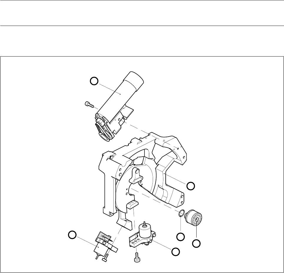
Fig. 9.2.2 Valve adjustment drives, turning station and distributor of the revolver head
1 Turning station
2 Reject circuit valve adjustment drive
3 Placement circuit valve adjustment drive
4 Distributor
5O-ring
6 Back part of placement head
3
5
2
1
4
6