F5 SERVICE MAUNAL.pdf - 第315页
SIPLACE 80S-20/F4 Service Manual 9 12-Segment Revolver Head (10000) Edition 07/97 9.4 Vacuum Generator Block 9 - 19 ● Remo ve the fr ont part of the pla cement he ad (see section 9.1. 7 ). ● Careful ly rem ove the v acuu…
9 12-Segment Revolver Head (10000) SIPLACE 80S-20/F4 Service Manual
9.4 Vacuum Generator Block Edition 07/97
9 - 18
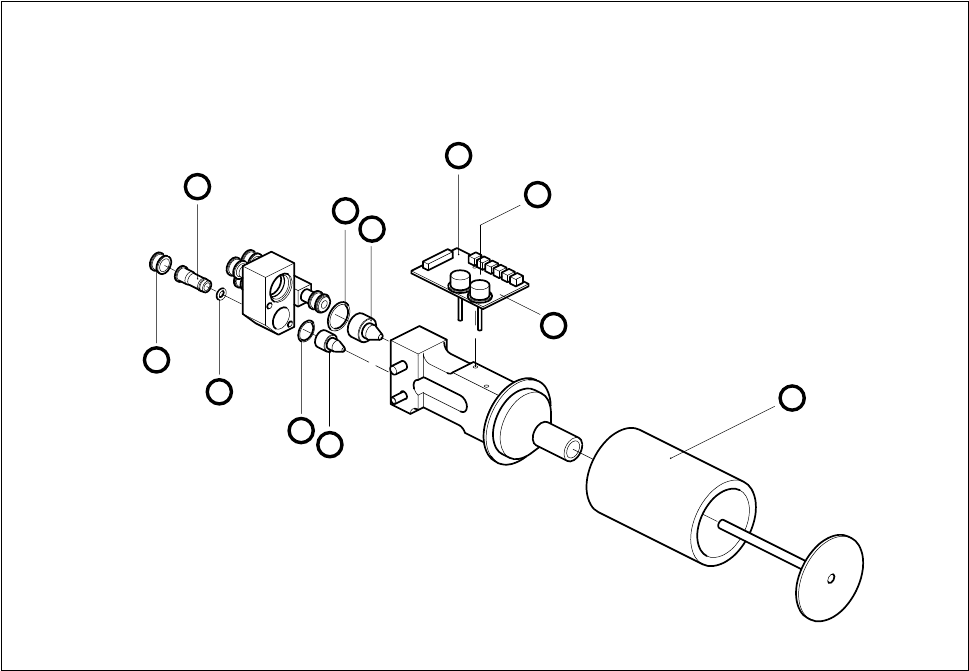
● Undo the hexagon spacer and remove the vacuum board (see Fig. 9.4.1).
● When installing, proceed in the reverse sequence of operations.
– No adjustment of settings will be necessary.
Fig. 9.4.1 Vacuum generator block
1 Silencer A Undo M 2.5x5 hexagon socket screw
2 Vacuum measurement board B Undo M2.5x10 hexagon distance bolt
3 Holding circuit vacuum nozzle using a fork wrench, width across flats 4
4 O-ring 14 x 1.5
5 Collet bush
6 Clamping ring
7O-ring
8 O-ring 10 x 1.5
9 Placement circuit vacuum nozzle
9.4.4 Cleaning the Vacuum Distributor and Vacuum Distributor Disk
Spare parts
Vacuum distributor, from item no. 00319827S02
Vacuum distributor disk, from item no. 00319351-02
2
B
A
9
8
7
6
5
4
3
1
SIPLACE 80S-20/F4 Service Manual 9 12-Segment Revolver Head (10000)
Edition 07/97 9.4 Vacuum Generator Block
9 - 19
● Remove the front part of the placement head (see section 9.1.7).
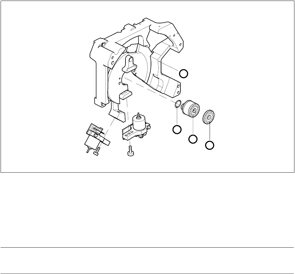
● Carefully remove the vacuum distributor.
● Clean or replace as appropriate the two o-rings or the vacuum distributor (see Fig. 9.4.2).
● Pull the vacuum distributor disk off the front of the placement head.
● Clean the vacuum distributor disk and lightly grease its back with Unisilkon.
● When you fit the vacuum distributor disk watch out for the two guide pins.
Fig. 9.4.2 Vacuum distributor and vacuum distributor disk
1O-ring
2 Vacuum distributor
3 Vacuum distributor disk in placement head front part
4 Placement head back part
● When installing, proceed in the reverse sequence of operations.
NOTE
When you insert the vacuum distributor disk make sure the o-rings are seated firmly.
3
2
1
4

9 12-Segment Revolver Head (10000) SIPLACE 80S-20/F4 Service Manual
9.4 Vacuum Generator Block Edition 07/97
9 - 20
9.4.5 Replacing the RSF Encoder for the Turning Station
PLEASE NOTE
This work may only be carried out by Siemens service technicians or by the customer’s appropriately trained
personnel.
Spare parts
RSF encoder for turning station, from item no. 00319907S01
Test equipment
Precision test pin, dia 1.4, from item no. 00326160-01
Precision test pin, dia. 1.5
, from item no. 00326161-01
Precision test pin, dia. 1.6
, from item no. 00326162-01
Star gauge, (star zero point gauge) from item no. 00326164-01
● Remove the X7 connector from the distributor board.
● Undo the two hexagon socket screws (M2.5 x 5) of the encoder conversion board.
● Undo the two hexagon socket screws (2.5 x 8) and remove the entire encoder.
● To reinstall reverse the sequence of operations.
Adjustment work
● Fix the star using the star gauge (star zero point gauge).
● For correct adjustment of the distance between the encoder and the segment underside use the precision
test pin, dia. 1.5mm.
Check the correct adjustment with the two other precision test pins:
– When using the precision test pin with a dia. of 1.6 mm you must not be able to slide the pint in-
between the encoder and the segment underside.
– When using the precision test pin with a dia. of 1.4 mm you have to be able to easily insert the test pin.