F5 SERVICE MAUNAL.pdf - 第346页
11 Control Unit SIPLACE 80S-20/F4 Service Manual 11.1 Replacing Modules E dition 03/97 11 - 4 1 1.1.3 Rep lacing the Network Adapter Spare par ts Network adapter, f rom item no. 003 20413-01 ● Unplug th e ribbon cabl e f…
SIPLACE 80S-20/F4 Service Manual 11 Control Unit
Edition 03/97 11.1 Replacing Modules
11 - 3
11.1 Replacing Modules
WARNING
QQQ
Do not remove or insert any electrical modules unless the machine has been switched off and disconnected
from the power supply.
NOTE
For the work which follows you should comply with the safety instructions and the ESD guidelines (see Sec-
tion 1).
11.1.1 Auxiliary Materials and Equipment Required
– 1 set of screwdrivers
– ESD armband
– Catalog of spare parts
11.1.2 Preparatory Work
● Switch off the machine at the main switch and disconnect it from the main power supply.
● Open the control cabinet door.
NOTE
See Section 2 for diagrams of the control unit.
11 Control Unit SIPLACE 80S-20/F4 Service Manual
11.1 Replacing Modules Edition 03/97
11 - 4
11.1.3 Replacing the Network Adapter
Spare parts
Network adapter, from item no. 00320413-01
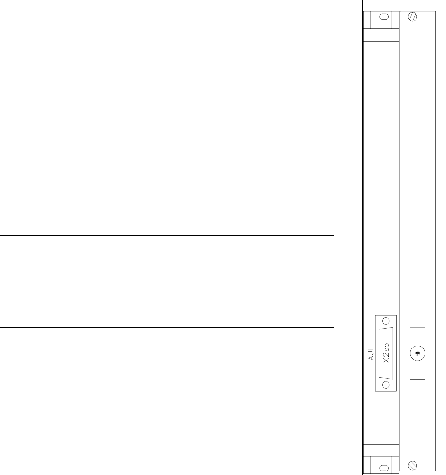
● Unplug the ribbon cable from the front cover (plugs x2-sp;
see Fig. 11.1.1).
● Undo and remove the board’s front cover mounting screws (2 slotted-head
screws).
● Press the holders apart so that the plug-in contacts release. Carefully pull
out the board and place it on an ESD-checked surface.
● Check the jumper setting on the new LAN board and, if necessary, set the
jumpers in the same way they are set on the old board.
● To fit the new board proceed in the reverse sequence of operations.
● Insert the old card into container which will be used for transporting it (for
example, an ESD envelope).
WARNING
QQ
Make sure that the ribbon cable on the righthand side of the network board
does not get pinched or damaged.
NOTE
No setting work or modification to the software configuration is required fol-
lowing the installation of the new board.
Fig. 11.1.1 Network adapter
SIPLACE 80S-20/F4 Service Manual 11 Control Unit
Edition 03/97 11.1 Replacing Modules
11 - 5
11.1.4 Replacing Computer M44 (Machine
Controller)
Spare parts
Computer MC AMS M44-A66, from item no. 00318558-01
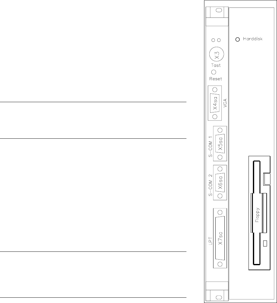
● Disconnect all plug-in connections on the front cover of the
machine controller (plug x3, x4 sa, x5 sa; see Fig. 11.1.2).
● Undo the MC board’s front cover mounting screws (2 slotted-
head screws) and the hard disk / floppy disk board mounting
screws (4 slotted head screws).
NOTE
The MC and hard disk / floppy disk boards are connected by two
short ribbon cables.
● Carefully pull out the MC and the hard disk / floppy disk boards
simultaneously.
● Carefully pull out the boards and place them on an ESD-
checked surface.
● Check the wrap wiring of the new machine controller against the
list (see Section 11.3).
● Disconnect the connecting cable between the machine control-
ler and the hard disk / floppy disk board.
● Connect the new MC board to the hard disk / floppy disk board.
● To fit the boards proceed in the reverse sequence of operations.
NOTE
When inserting the connecting plugs make sure you have the cor-
rect slots on the front panel.
Should you have lost the setup data for the M44 see Section 11.2.
Fig. 11.1.2 Computer M44
hard disk drive/
floppy drive