F5 SERVICE MAUNAL.pdf - 第369页
SIPLACE 80S -20/F4/F5 S ervice Man ual 12 Vision systems Edition 09/99 12.4 Replacing the coplanarity laser m odule (SIPLACE 80F) 12 - 17 Key to Fig. 12.4.3 6HWWLQJ Z RUN ● Calibr ate the coplanar ity mod ule wi…
12 Vision systems SIPLACE 80S-20/F4/F5 Service Manual
12.4 Replacing the coplanarity laser module (SIPLACE 80F) Edition 09/99
12 - 16
DANGER
Any unauthorized tampering with or modifications to the equipment will render the factory safety warranty
void !
In addition, the user must comply with the guidelines of the Hauptverband der Berufsgenossenschaften
- VBG 93. In other words:
- Registration with the industrial accident insurance association
- Appointment of a laser safety officer
- Drawing up guidelines for the use of the module
In all other countries the corresponding national guidelines and standards must be complied with:
7RROVLQVSHFWLRQPHDVXULQJDQGWHVWHTXLSPHQWUHTXLUHG
6SDUHSDUWV
5HPRYLQJWKHFRSODQDULW\PRGXOH
● Remove the component changeover table as described in Section 12.1, page 12 - 5.
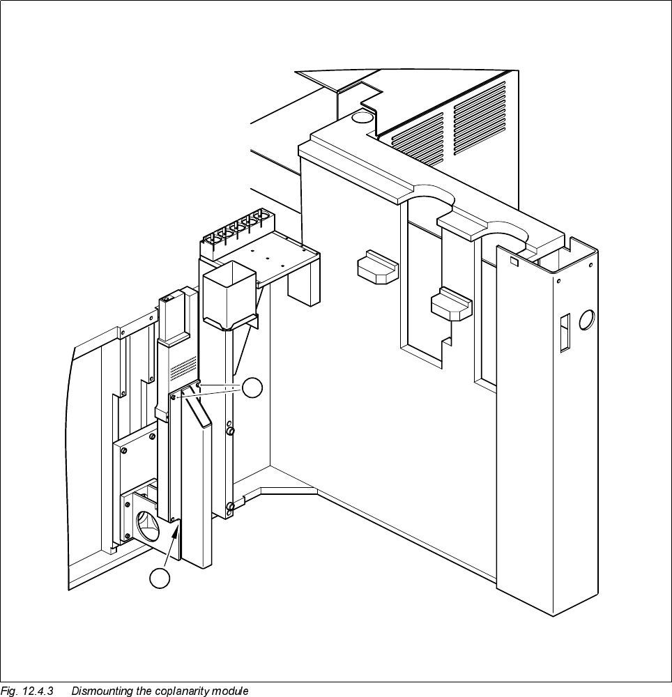
● Undo the two M4 x 10 hexagon socket screws (see A in Fig. 12.4.3) and lift the coplanarity module up and
away.
,QVWDOOLQJWKHFRSODQDULW\PRGXOH
● Place the coplanarity module in position.
● Slide the 0.5 mm feeler gauge between the module and the support (see B in Fig. 12.4.3).
● Fasten the module back in place using the M4 x 10 hexagon socket screws.
Country Germany Europe International
Standard DIN EN 60825-1/2 EN 60825-1/2 IEC 825-1/2
Set of hexagon socket screwdrivers
Feeler gauge 0.5 mm
SITEST program
'HVLJQDWLRQ )URPLWHPQXPEHU
Coplanarity module SIPLACE 80F 00306397-02
SIPLACE 80S-20/F4/F5 Service Manual 12 Vision systems
Edition 09/99 12.4 Replacing the coplanarity laser module (SIPLACE 80F)
12 - 17
Key to Fig. 12.4.3
6HWWLQJZRUN
● Calibrate the coplanarity module with the aid of the SITEST program
● Once you have completed your setting work, fit the component changeover table back again.
A 2 M4 x 10 hexagon socket screws
B 0.5 mm feeler gauge between module and support
B
A
12 Vision systems SIPLACE 80S-20/F4/F5 Service Manual
12.5 Replacing the undergantry PCB camera Edition 09/99
12 - 18
5HSODFLQJWKHXQGHUJDQWU\3&%FDPHUD
7RROVLQVSHFWLRQPHDVXULQJDQGWHVWHTXLSPHQWUHTXLUHG
6SDUHSDUWV
5HPRYLQJWKH3&%XQGHUJDQWU\FDPHUD
● Move the gantry whose undergantry camera is to be replaced until the gantry is positioned over the board
conveyor belt.
DANGER
Switch the machine off and disconnect it from the main power supply.
● Starting at the center, remove about 6 feeder modules from the components table above which the under-
gantry camera is to be replaced. Note down the order of the feeder modules you removed or have the set-
up printed out by the line computer. This will help prevent set-up errors later on.
● Place the mirror on the unoccupied location.
● Slide the gantry above the mirror by hand.
● Undo the four cable clips for the board camera cable from the revolver head and gantry
(see A in Fig. 12.5.1).
● Disconnect the plug of the board camera cable from plug X8 of conversion board C0005 (see B in Fig.
12.5.1).
● Pull the board camera cable out of the cable clips.
● With the aid of the mirror ascertain the position of the mounting screws.
● Undo the three M2 x 10 hexagon socket screws (see A in Fig. 12.5.2 page 12 - 20) which fasten the board
undergantry camera (see ➁ in Fig. 12.5.2 page 12 - 20) to the gantry (see
➀
in Fig. 12.5.2). While doing so
hold the board camera with your free hand.
Set of hexagon socket screwdrivers
Mirror
SITEST program
'HVLJQDWLRQ )URPLWHPQXPEHU
PCB optical module 00315224-01