F5 SERVICE MAUNAL.pdf - 第430页
13 6-Segment Revolver Head (8000) SIPLACE 80S-20/F4 Service Manual 13.4 Vacuum Generator Block Edition 07/97 13 - 16 13.4 V acuum Generator Block 13.4.1 Replacing the V enturi Nozzles and the O-Ring Spare par ts V acuum …
SIPLACE 80S-20/F4 Service Manual 13 6-Segment Revolver Head (8000)
Edition 07/97 13.3 Replacing the Distributor Board and the Components Camera
13 - 15
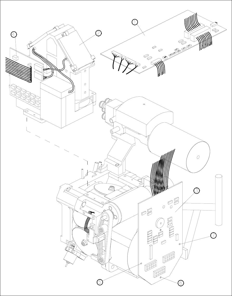
Fig. 13.3.1 Replacing distributor board and the components camera
Key to Fig. 13.3.1
1 Small axis conversion board 5 M3x9 hexagon spacer
2 Component camera 6 M3x10 hexagon spacer
3 Distributor board 7 M3x7 hexagon spacer
4 Y0021 components camera illumination board

13 6-Segment Revolver Head (8000) SIPLACE 80S-20/F4 Service Manual
13.4 Vacuum Generator Block Edition 07/97
13 - 16
13.4 Vacuum Generator Block
13.4.1 Replacing the Venturi Nozzles and the O-Ring
Spare parts
Vacuum nozzle, 1.5 dia. (holding circuit) from item no. 00319420S02
O-ring 14 x 1.5 NBR 70B (holding circuit) from item no. 00320048S01
Vacuum nozzle (placement circuit) from item no. 00319423S02
O-ring 10 x 1.5, NBR 70B (placement circuit) from item no. 00320047S01
● Disconnect the compressed air lines from the vacuum generator.
● Undo the two hexagon socket screws (M3 x 22) and remove the distributor.
● Carefully remove the two venturi nozzles together with their o-rings (see Fig. 13.4.1).
● Replace or clean the parts as appropriate.
● Before fitting the o-rings, lightly grease them with Unisilkon.
● To re-install, proceed in the reverse sequence of operations.
NOTE
When inserting the venturi nozzles make sure that the o-rings are seated firmly in the cutouts.
13.4.2 Replacing the Silencer
Spare parts
Silencer, from item no. 00320964-01
● Detach the silencer by hand by turning it anticlockwise.
● Pull out the threaded rod and remove the funnel from the silencer (see Fig. 13.4.1).
● Replace the silencer with a new one.
● When installing, proceed in the reverse sequence of operations.
SIPLACE 80S-20/F4 Service Manual 13 6-Segment Revolver Head (8000)
Edition 07/97 13.4 Vacuum Generator Block
13 - 17
13.4.3 Replacing the Vacuum Board
Spare parts
Vacuum board SP6/12, from item no. 00321216S03
● Disconnect plug-in connection X10 from head board C0005.
● Carefully pull the two hoses off the compressed air sensors for the placement and holding circuits.
● Undo the hexagon socket screw M 2.5 x 5 (A) (see Fig. 13.4.1) and the hexagon spacer bolt M2.5x10 (B)
(see Fig. 13.4.1) using a fork wrench, width across flats 4.
● Undo the hexagon spacer and remove the vacuum board (see Fig. 13.4.1).
● When installing, proceed in the reverse sequence of operations.
– No adjustment of settings will be necessary.
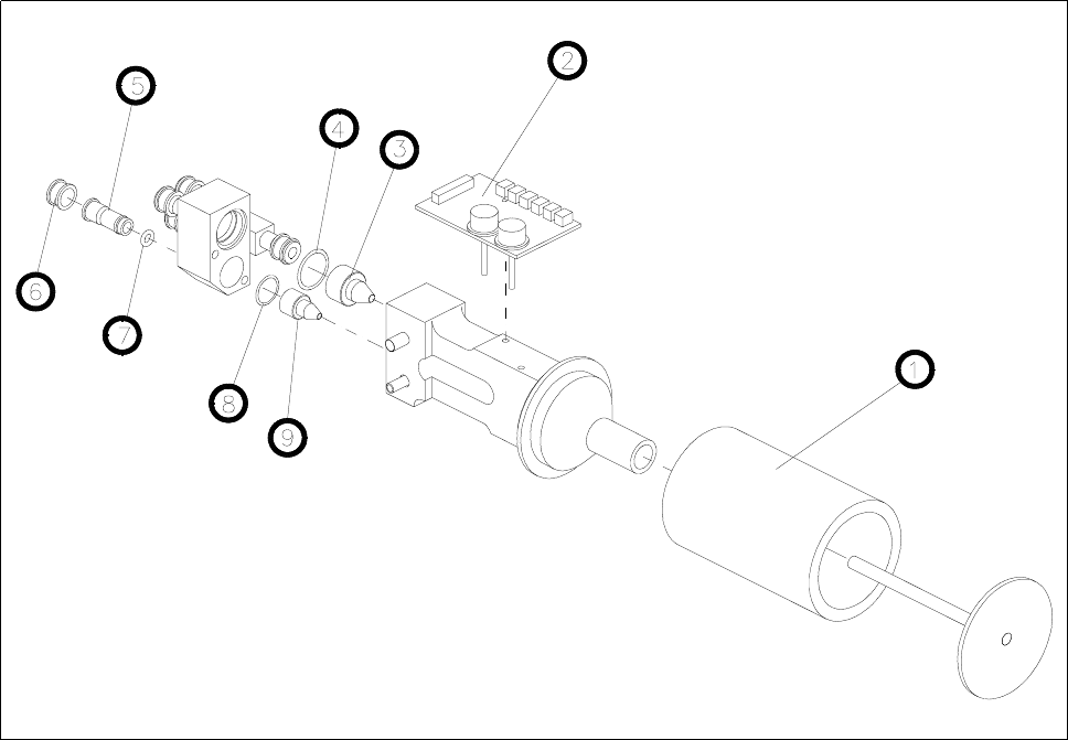
Fig. 13.4.1 Vacuum generator block
1Silencer
2 Vacuum measurement board
3 Holding circuit vacuum nozzle
4 O-ring 14 x 1.5
5Collet bush
6 Clamping ring
7 O-ring
8 O-ring 10 x 1.5
9 Placement circuit vacuum nozzle