F5 SERVICE MAUNAL.pdf - 第433页
SIPLACE 80S-20/F4 Service Manual 13 6-Segment Revolver Head (8000) Edition 07/97 13.4 Vacuum Generator Block 13 - 19 13.4.5 Replacing the RSF Encod er for the T urning Station PLEASE NOT E This wor k may o nly be c arrie…
13 6-Segment Revolver Head (8000) SIPLACE 80S-20/F4 Service Manual
13.4 Vacuum Generator Block Edition 07/97
13 - 18
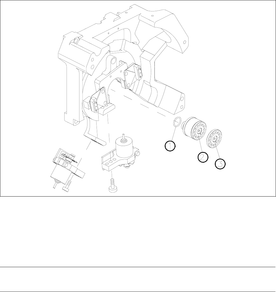
13.4.4 Cleaning the Vacuum Distributor and Vacuum Distributor Disk
Spare parts
Vacuum distributor, from item no. 00319827S02
Vacuum distributor disk, from item no. 00319351-02
● Remove the front part of the placement head (see section 13.1.7).
● Carefully remove the vacuum distributor.
● Clean or replace as appropriate the two o-rings or the vacuum distributor (see Fig. 13.4.2).
● Pull the vacuum distributor disk off the front of the placement head.
● Clean the vacuum distributor disk and lightly grease its back with Unisilkon.
● When you fit the vacuum distributor disk watch out for the two guide pins.
Fig. 13.4.2 Vacuum distributor and vacuum distributor disk
1O-ring
2 Vacuum distributor
3 Vacuum distributor disk in placement head front part
4 Placement head back part
● When installing, proceed in the reverse sequence of operations.
NOTE
When you insert the vacuum distributor disk make sure the o-rings are seated firmly.

SIPLACE 80S-20/F4 Service Manual 13 6-Segment Revolver Head (8000)
Edition 07/97 13.4 Vacuum Generator Block
13 - 19
13.4.5 Replacing the RSF Encoder for the Turning Station
PLEASE NOTE
This work may only be carried out by Siemens service technicians or by the customer’s appropriately trained
personnel.
Spare parts
RSF encoder for turning station, from item no. 00319907S01
Test equipment
Precision test pin, dia 1.4, from item no. 00326160-01
Precision test pin, dia. 1.5
, from item no. 00326161-01
Precision test pin, dia. 1.6
, from item no. 00326162-01
Star gauge from item no. 00326164-01
● Remove the X7 connector from the distributor board.
● Undo the two hexagon socket screws (M2.5 x 5) of the encoder conversion board.
● Undo the two hexagon socket screws (2.5 x 8) and remove the entire encoder (see item 8 in Fig. 13.5.1,
page 13 - 24.
● To reinstall reverse the sequence of operations.
Adjustment work
● Fix the star using the star gauge.
● For correct adjustment of the distance between the encoder and the segment underside use the precision
test pin, dia. 1.5mm.
Check the correct adjustment with the two other precision test pins:
– When using the precision test pin with a dia. of 1.6 mm you must not be able to slide the pint in-
between the encoder and the segment underside.
– When using the precision test pin with a dia. of 1.4 mm you have to be able to easily insert the test pin.

13 6-Segment Revolver Head (8000) SIPLACE 80S-20/F4 Service Manual
13.5 Z Axis Unit Edition 07/97
13 - 20
13.5 Z Axis Unit
13.5.1 Replacing the ’Z Axis Top’ Sensor
PLEASE NOTE
This work may only be carried out by Siemens service technicians or by the customer’s appropriately trained
personnel.
Spare parts
Positioning unit, from item no. 00321213S02
● Disconnect plug-in connection X10 from distributor board.
● Undo the two recessed-head screws (M2 x 5) and remove the ribbon cable holders.
● Undo the two slotted head screws (M1.6 x 4) and remove the ’z sensor top’ board (see Fig. 13.5.1).
● When re-installing, proceed in the reverse sequence of operations.
● Carry out z-axis zero point correction again (see section 13.5.3).
NOTE
When you fit the ribbon cable holder make sure that you do not pinch the cables.
13.5.2 Replacing the Motor for the Z Axis
PLEASE NOTE
This work may only be carried out by Siemens service technicians or by the customer’s appropriately trained
personnel.
Spare parts
Motor z axis, from item no. 00319891S01
Test equipment
Belt tension measuring device TSM, from item no. 00326015-01
’Measure Belt Tension’ Instructions
● Disconnect plug-in connections X3 and X4 from the distributor board.
● Undo the four hexagon socket head screws (3 x M3 x 5, see pos. 2 Fig. 13.5.1) and 1 M4 x 10 at the motor
mounting (see pos. 6, Fig. 13.5.1).