SU_UM_TME20822_EN.pdf - 第12页
12 Smart-UPS S MTL 22 00/3000 RMI2UC/RMI2UCNC Inst alla tion EN TME2 08 22 – 08/2 023 Installation Place ment Do not place the UPS where there is ex cessive dust, t emperature an d humidity . N ote that temperature in ex…

11
Product Front View
Smart-UPS SMTL 2200/3000 RMI2UC/RMI2UCNC
EN TME20822 – 08/2023
Rear panel features
SMTL2200RMI2UC/SMTL3000RMI2UC
SMTL2200RMI2UCNC/SMTL3000RMI2UCNC
SmartSlot for APC management card
SmartConnect Ethernet port
Refer to “SmartConnect” on page 14
for details.
Outlet
Controlled outlet group (Group1)
Outlets
Serial port
Input circuit breaker
USB port
UPS input
AP9641 Network Management
Card (NMC).
NOTE: Refer the user manual of the
NMC card for details of the ports.
Chassis ground connection screw
EPO connector
su1 a354
su1 a355
12
Smart-UPS SMTL 2200/3000 RMI2UC/RMI2UCNC
Installation
EN TME20822 – 08/2023
Installation
Placement
Do not place the UPS where there is excessive dust, temperature and humidity. Note
that temperature in excess of 25
o
C may have an adverse effect on battery and UPS
life. All vents on the side or rear of the UPS should be free of obstructions.
The UPS is heavy. It is suggested that the batteries be removed for easier installation.
The UPS should be placed near the bottom of the rack.
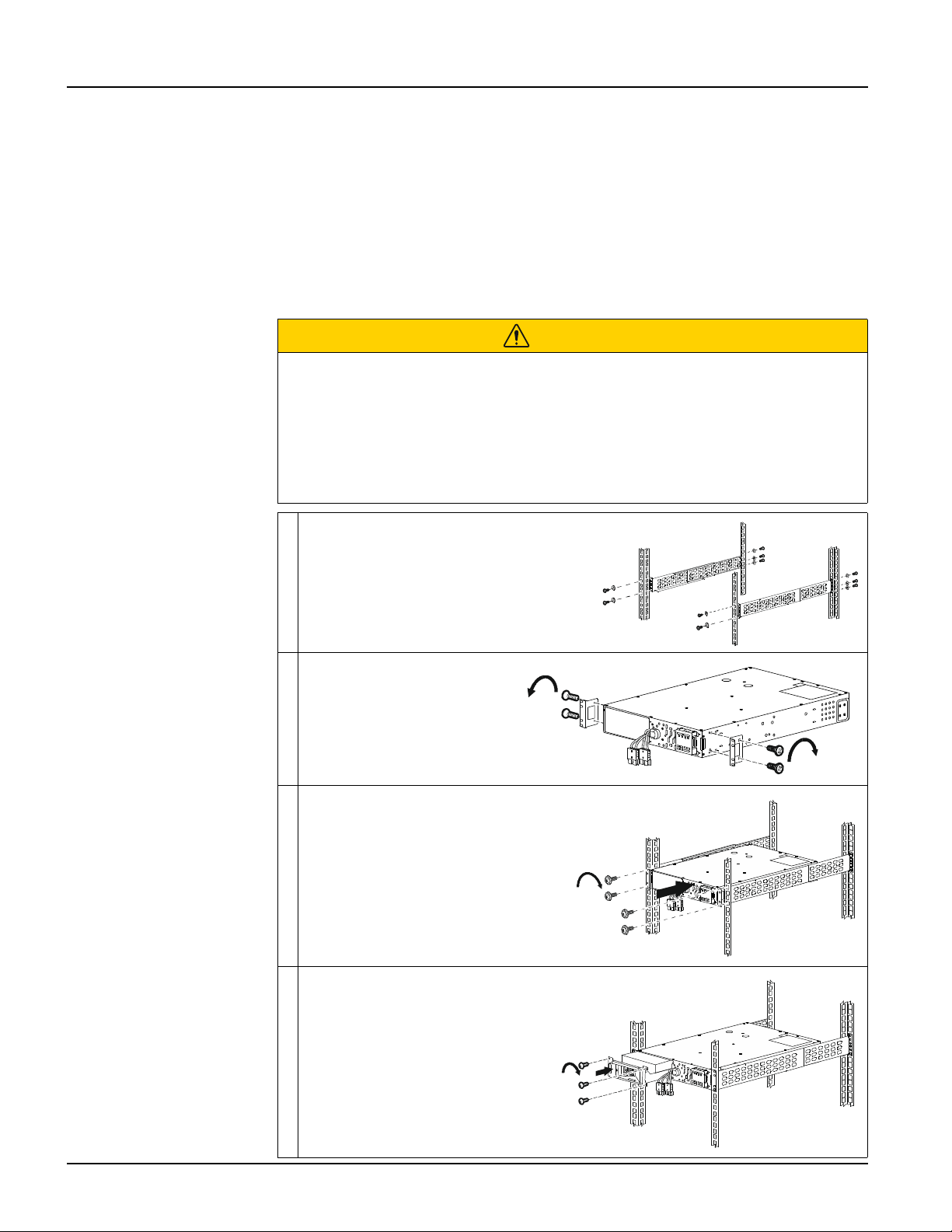
Rack-mounting
CAUTION
RISK OF FALLING EQUIPMENT
• The equipment is heavy.
• Always practice safe lifting techniques adequate for the weight of the equipment.
• Use the battery module handle to slide the battery modules in or out of the UPS.
• Do not use the battery module handle to lift or carry the battery module.
Failure to follow these instructions could result in equipment damage and
minor or moderate injury.
Install the rail-kit on the rack, using flat
head screws (10x) and washers (10x)
(supplied).
Install the rack-mount
brackets on the UPS, using
the flat head screws (4x)
(supplied).
Install the UPS on the rack, using the
ornamental screws (4x) (supplied)
Install the battery module in the
UPS. Tighten the 3 screws to
secure the battery to the UPS.
s
u
1
2
4
2
a
x2x2
x2
s
u
1
2
4
3
a
4x
s
u
1
2
4
4
a
s
u
1
2
4
5
a
3x
13
Installation
Smart-UPS SMTL 2200/3000 RMI2UC/RMI2UCNC
EN TME20822 – 08/2023
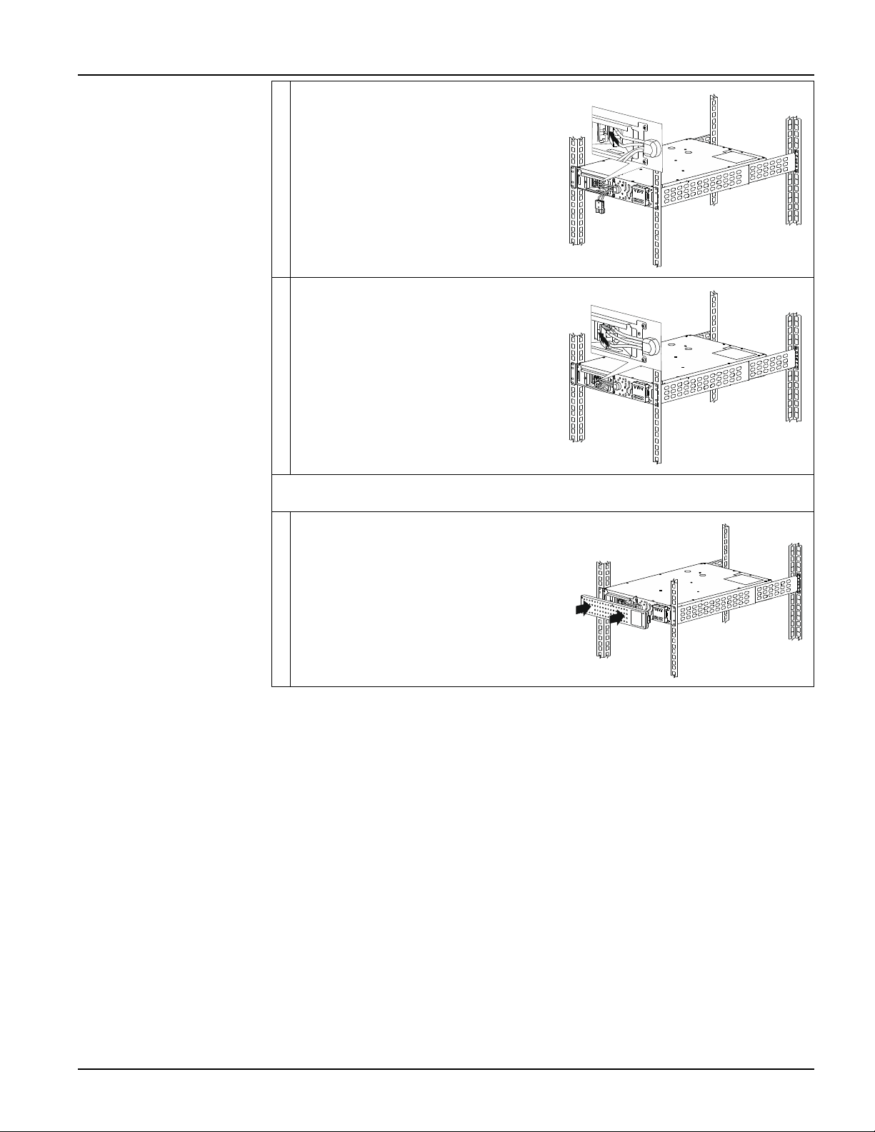
Connect the black color internal battery
connector to the black color receptacle in
the battery module. Be sure that the
connection is secure.
Connect the red color internal battery
connector to the red color receptacle in
the battery module. Be sure that the
connection is secure.
NOTE: Pull the strap provided on the connectors for disconnecting the battery.
Do not pull the wires.
Install the bezel.
s
u
1
2
4
6
a
s
u
1
2
4
7
a
s
u
1
2
4
8
a