SU_UM_TME20822_EN.pdf - 第13页
13 Inst alla tion Smart-UPS SMTL 220 0/3000 RMI2UC/RMI2UCNC EN T ME2 0822 – 08 /202 3 Connec t t he black colo r internal battery conn ect or to the black color receptacle i n the battery module. Be sure that the conn …
12
Smart-UPS SMTL 2200/3000 RMI2UC/RMI2UCNC
Installation
EN TME20822 – 08/2023
Installation
Placement
Do not place the UPS where there is excessive dust, temperature and humidity. Note
that temperature in excess of 25
o
C may have an adverse effect on battery and UPS
life. All vents on the side or rear of the UPS should be free of obstructions.
The UPS is heavy. It is suggested that the batteries be removed for easier installation.
The UPS should be placed near the bottom of the rack.
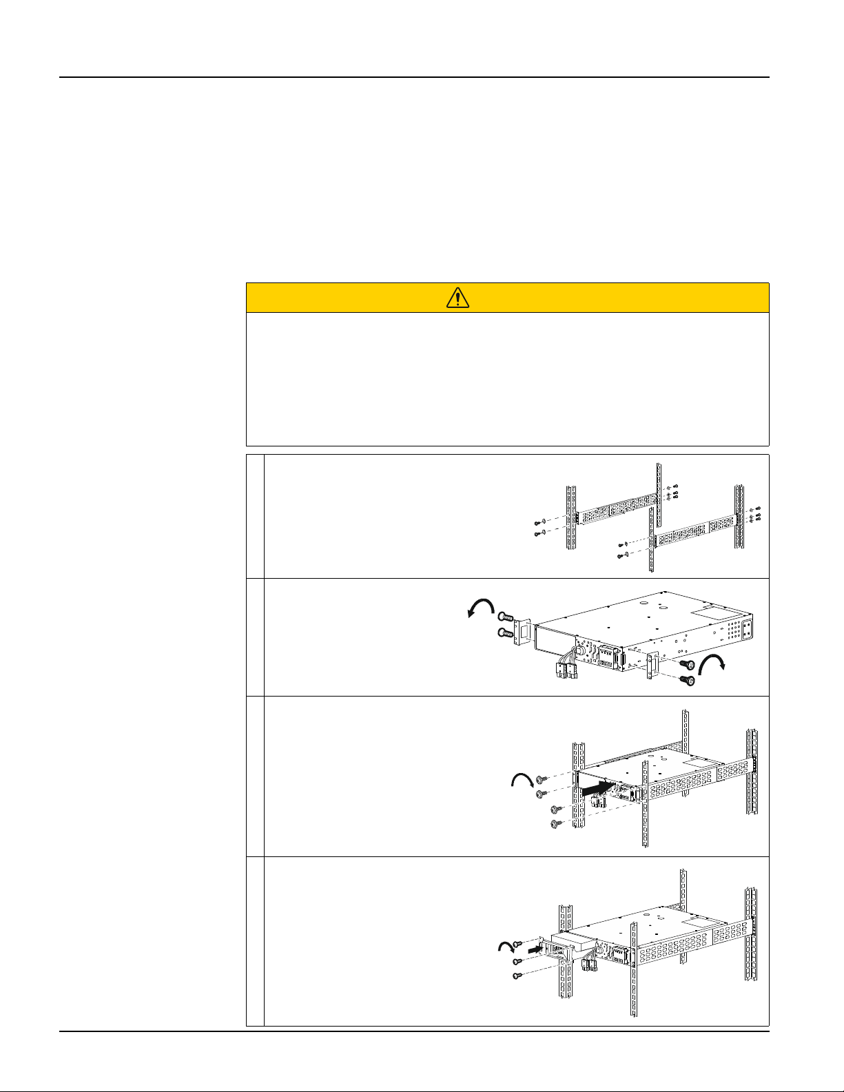
Rack-mounting
CAUTION
RISK OF FALLING EQUIPMENT
• The equipment is heavy.
• Always practice safe lifting techniques adequate for the weight of the equipment.
• Use the battery module handle to slide the battery modules in or out of the UPS.
• Do not use the battery module handle to lift or carry the battery module.
Failure to follow these instructions could result in equipment damage and
minor or moderate injury.
Install the rail-kit on the rack, using flat
head screws (10x) and washers (10x)
(supplied).
Install the rack-mount
brackets on the UPS, using
the flat head screws (4x)
(supplied).
Install the UPS on the rack, using the
ornamental screws (4x) (supplied)
Install the battery module in the
UPS. Tighten the 3 screws to
secure the battery to the UPS.
s
u
1
2
4
2
a
x2x2
x2
s
u
1
2
4
3
a
4x
s
u
1
2
4
4
a
s
u
1
2
4
5
a
3x
13
Installation
Smart-UPS SMTL 2200/3000 RMI2UC/RMI2UCNC
EN TME20822 – 08/2023
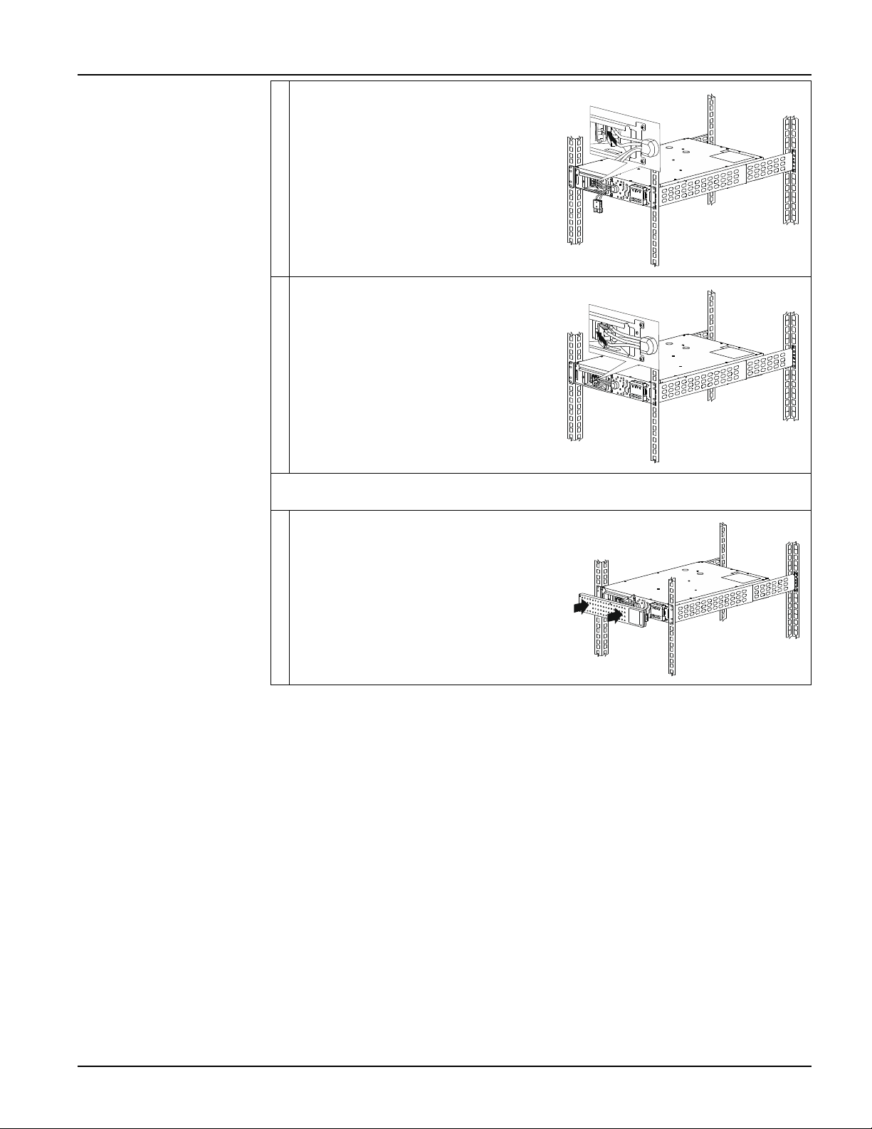
Connect the black color internal battery
connector to the black color receptacle in
the battery module. Be sure that the
connection is secure.
Connect the red color internal battery
connector to the red color receptacle in
the battery module. Be sure that the
connection is secure.
NOTE: Pull the strap provided on the connectors for disconnecting the battery.
Do not pull the wires.
Install the bezel.
s
u
1
2
4
6
a
s
u
1
2
4
7
a
s
u
1
2
4
8
a
14
Smart-UPS SMTL 2200/3000 RMI2UC/RMI2UCNC
SmartConnect
EN TME20822 – 08/2023
SmartConnect
SmartConnect Ethernet Port allows you to monitor the health and status of your UPS
from any device connected to the Internet. Availability of features varies by terms of
use. Access the terms of use at https://smartconnect.apc.com.
Refer to "EcoStruxure™ IT SmartConnect" below for details.
EcoStruxure™ IT SmartConnect
The Web Portal allows you to remotely view the status of your UPS, receive automatic
notifications about UPS events, and firmware updates. The features vary with terms of
use. Visit smartconnect.apc.com to learn more.
By connecting this product to the Internet using the SmartConnect Ethernet port, you
are agreeing to the APC SmartConnect Terms of Use and Data Privacy Notice, as
found at smartconnect.apc.com/terms-and-privacy. The Schneider Electric Data
Privacy Policy can also be found at smartconnect.apc.com/terms-and-privacy.
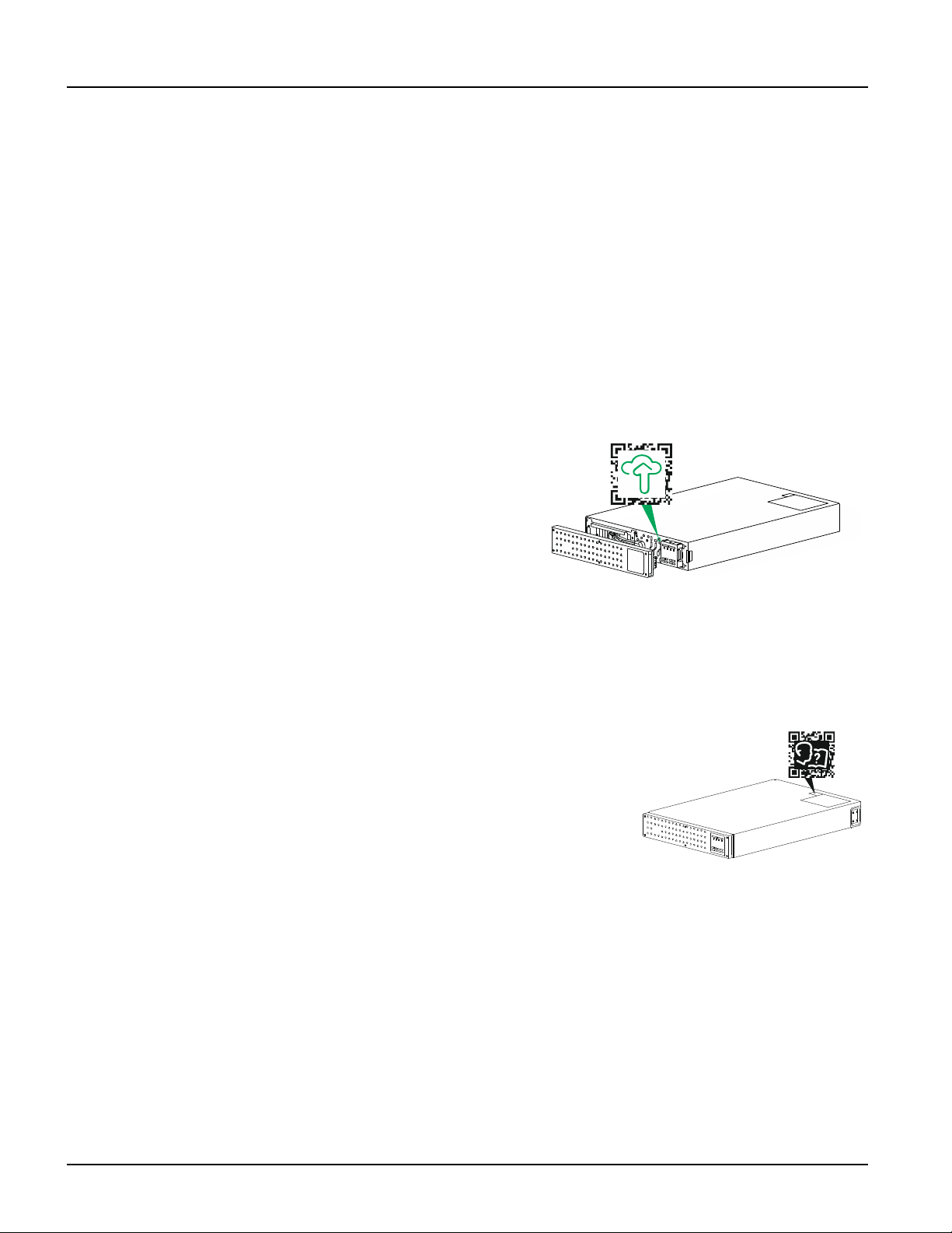
Log onto smartconnect.apc.com or
scan the QR code to begin the
registration process. The QR code is
located behind the front bezel of the
UPS.
Allow a few minutes for the Ethernet
connection to get properly
established before you can complete
the registration process.
For instructions on how to register your SmartConnect-compatible UPS, visit
smartconnect-support.apc.com.
Location of product information QR code
Location of product information QR Code is shown
in the illustration below. Scan the QR code for more
information of the product.
s
u
1
2
4
9
a
s
u
1
2
5
4
a