SU_UM_TME20822_EN.pdf - 第16页
16 Smart-UPS S MTL 22 00/3000 RMI2UC/RMI2UCNC Start up Se tti ngs EN TME2 08 22 – 08/2 023 St art up Setti ngs When the U PS is powered on for th e f irst time the d isplay interface displays the S etup Wizard to configu…
15
Connect to equipment and utilities
Smart-UPS SMTL 2200/3000 RMI2UC/RMI2UCNC
EN TME20822 – 08/2023
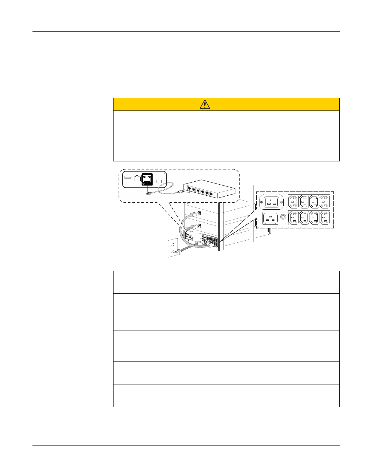
Connect to equipment and utilities
• Connect the UPS to the AC Mains outlet for 2 hours, for charging the battery, before
turning it ON for the first time.
• Upon receipt, connect the UPS to the AC Mains outlet for 2 hours to charge the
battery.
NOTE: The recommended shelf time of battery is not more than 12 months.
CAUTION
RISK OF DAMAGE TO EQUIPMENT OR PERSONNEL
• Adhere to all local and national electrical codes.
• Wiring should be performed by qualified electrician.
• Always connect the UPS to a grounded outlet.
Failure to follow these instructions can result in injury.
Connect equipment to the outlets in the rear of the UPS. Some models are
equipped with controlled outlet groups. Refer to “Outlet group configuration
settings” on page 23 for details on the use of controlled outlet groups.
Connect the SmartConnect Ethernet port to your nearest network switch using the
Ethernet cable provided.
NOTE: By connecting the SmartConnect Ethernet port to the internet, you are
agreeing to the APC SmartConnect Terms of Use and Data Privacy Notice, as
found at smartconnect.apc.com/terms-and-privacy.
Connect the UPS input to AC power.
NOTE: Once UPS is connected to AC power, the display will be active.
Press the
UPS ON/OFF button on the UPS display to turn ON the UPS output.
NOTE: The On-Line LED will illuminate green when the output is ON.
When the UPS is powered on for the first time, the Start Up Settings Screen will
be displayed on the LCD display. Refer to “Start up Settings” on page 16 for
details.
Log onto www.smartconnect.apc.com or scan the QR code to launch the
registration process. The website includes instructions to setup your online
account, activate your warranty and begin monitoring your UPS remotely.
LINK/ACT
NETWORK
LINK/ ACT
NET W O RK
s
u
1
3
5
8
a
16
Smart-UPS SMTL 2200/3000 RMI2UC/RMI2UCNC
Start up Settings
EN TME20822 – 08/2023
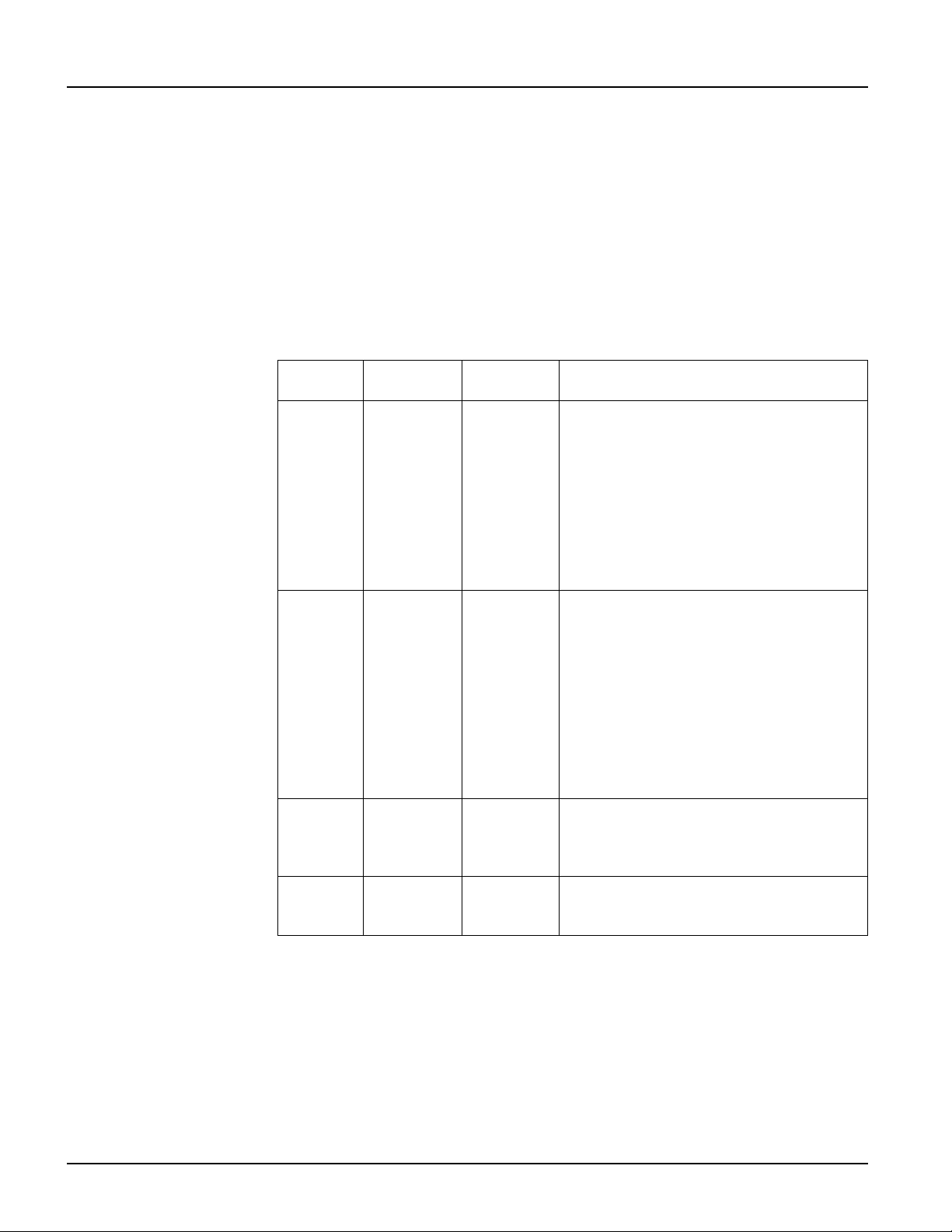
Start up Settings
When the UPS is powered on for the first time the display interface displays the Setup
Wizard to configure the start up settings. Configuration can also be performed using
PowerChute™ software.
NOTE: If the start up settings asked by the Setup Wizard are not selected completely,
turning on UPS output is inhibited. The Setup Wizard will disappear from the display if
the start up settings remain idle for 2 minutes. Pressing the
UPS ON/OFF button on the
front panel display will relaunch the Setup Wizard and allow completion of the start up
settings.
Use the
UP/DOWN buttons on the LCD display to scroll through the options and press
the
ENTER button to select the option.
Function
Factory
Default
Options Description
Language English English
French*
German*
Spanish*
Italian*
Portuguese*
Japanese*
The language for the display interface.
*Language options will vary by model.
Local
Power
Quality
Good Good
Fair
Poor
Select the quality of input AC power.
• If Good is selected, the unit will go on
battery power more often to provide the
cleanest power supply to the connected
equipment.
• If Poor is selected, the UPS will tolerate
more fluctuations in power and will go on
battery power less often.
If unsure of the local power quality, select
Good.
Menu
Type
Standard Standard
Advanced
The standard menu displays the most
commonly required menus for most users.
The advanced menus include all
parameters.
Today’s
Date
Manufacture
date
Use the
UP/DOWN buttons to enter the date,
and press the
ENTER button to complete the
setting.
17
Connect and Install Management Software
Smart-UPS SMTL 2200/3000 RMI2UC/RMI2UCNC
EN TME20822 – 08/2023
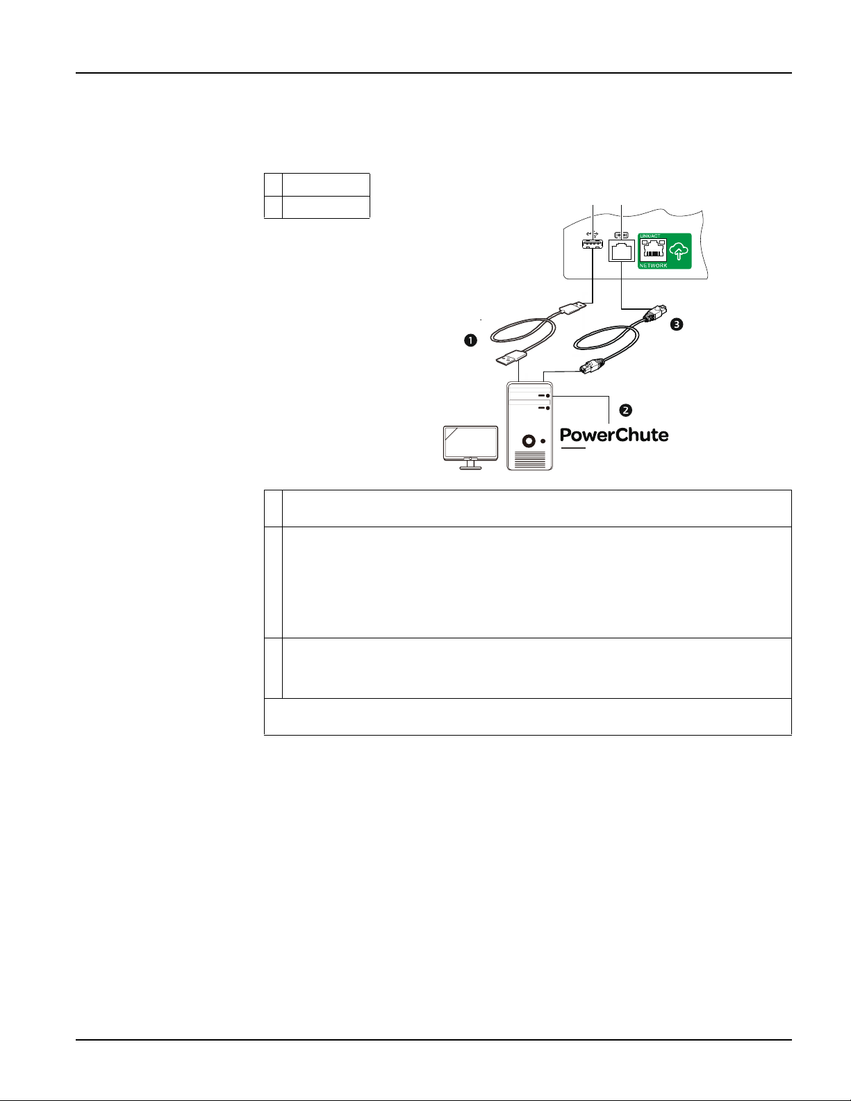
Connect and Install Management Software
Smart-UPS is provided with PowerChute UPS Management Software for unattended
operating system shutdown, UPS monitoring, UPS control and energy reporting. The
following diagram is a representation of a typical server installation.
USB Port
Serial Port
Connect the USB cable from the rear of the UPS to the protected device such as a
server.
For a server or other device with an operating system, download and install latest
version of the PowerChute Serial Shutdown from https://www.apc.com/pcss.
PowerChute Serial Shutdown supports graceful shutdown in the event of an
extended power outage.
NOTE: PowerChute is a 64-bit only application and cannot be installed on a 32-bit
operating system.
A built-in Serial port is also available for additional communication options with
serial cable.
NOTE: Serial and USB cannot be used at the same time.
Even more communication options are available via the built-in Smartslot. Refer to
www.apc.com for more information.
TM
SERIAL SHUTDOWN