SU_UM_TME20822_EN.pdf - 第25页
25 Confi guration Smart-UPS SMTL 220 0/3000 RMI2UC/RMI2UCNC EN T ME2 0822 – 08 /202 3 M odbus set tin gs Load Shed On Runtime Disabled • Sh ut dow n with delay • S hu t dow n immediat el y • Turn off immediat el y • Turn…
24
Smart-UPS SMTL 2200/3000 RMI2UC/RMI2UCNC
Configuration
EN TME20822 – 08/2023
In addition, the Main Outlet Group and the Controlled Outlet Group can be configured
to do the following:
• Turn ON or Turn OFF in a specified sequence
• Automatically turn OFF or shut down when various conditions occur
NOTE: If the Main and Controlled Outlet Groups are not configured, all the outlets on
the unit will still provide battery back-up power.
NOTE: The Main Outlet Group functions as a master switch. It will turn on first when
power is applied, and shut off last when there is a power outage and battery run-time
has been exhausted.
The Main Outlet Group must be turned on for the Controlled Outlet Group to turn on.
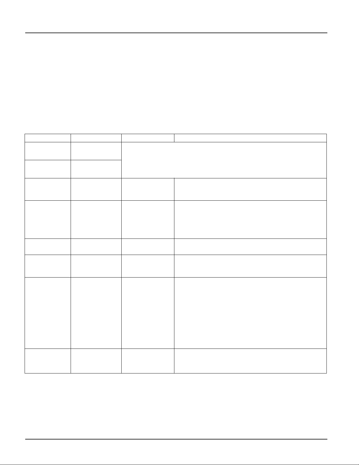
Setting Factory Default Options Description
Name String
Outlet Group
Outlet Group 1 Edit these names using an external interface, such as the Network
Management Card Web interface.
UPS Name
String
UPS Outlets
Turn On Delay 0 sec Set the value in
seconds
The amount of time the UPS or the Controlled Outlet
Group will wait between receiving the command to turn on
and the actual startup.
Turn Off Delay • 0 sec (UPS
Outlets)
• 90 sec
(Controlled
Outlet Groups)
Set the value in
seconds
The amount of time the UPS or the Controlled Outlet
Group will wait between receiving the command to turn off
and the actual shut down.
Reboot
Duration
8 sec Set the value in
seconds
The amount of time that the UPS or the Controlled Outlet
Group must remain off before it will restart.
Minimum
Return Time
0 sec Set the value in
seconds
The amount of battery runtime that must be available
before the UPS or the Controlled Outlet Group will turn
on.
Load Shed On
Battery
Disabled • Shutdown with
Delay
• Shutdown
immediately
• Turn off
immediately
• Turn off with
delay
• Disabled
When the unit switches to battery power, the UPS can
disconnect power to the Controlled Outlet Group to save
runtime.
To configure this delay time, use the L
OAD SHED TIME
WHEN ON BATTERY setting.
Load Shed
Time when On
Battery
Disabled Set the value in
seconds
The amount of time the outlets will function on battery
power before they will turn off.
25
Configuration
Smart-UPS SMTL 2200/3000 RMI2UC/RMI2UCNC
EN TME20822 – 08/2023
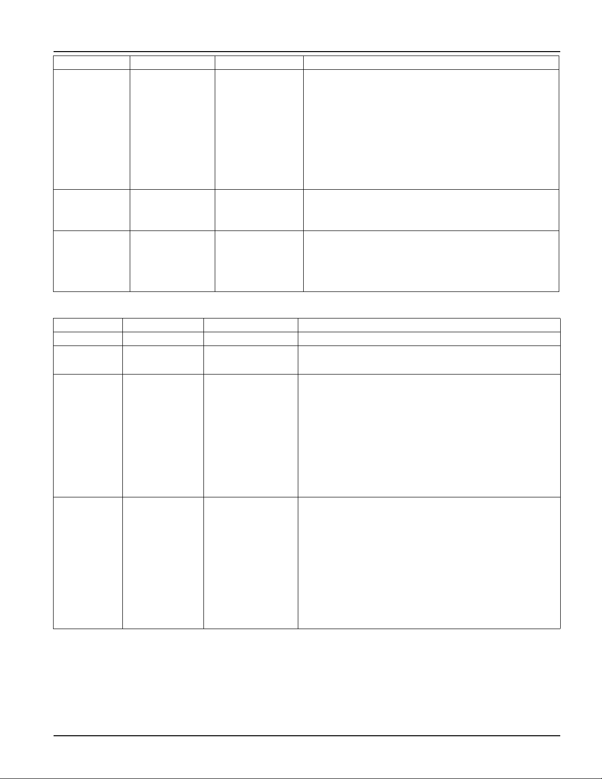
Modbus settings
Load Shed On
Runtime
Disabled • Shutdown with
delay
• Shutdown
immediately
• Turn off
immediately
• Turn off with
delay
• Disabled
When the battery runtime falls below the specified value,
the Controlled Outlet Group will turn off.
Configure this time using the L
OAD SHED RUNTIME
R
EMAINING setting.
Load Shed On
Runtime
Remaining
Disabled Set the value in
seconds
When the remaining runtime reaches this level, the
Controlled Outlet Group will turn off.
Load Shed on
Overload
Disabled • Disabled
• Enabled
In the event of an overload (greater than 100% output
power), the Controlled Outlet Group will immediately turn
off to conserve power for critical loads. The Controlled
Outlet Group will only turn on again with a manual
command.
Setting Factory Default Options Description
Slave ID 1 1- 223 Sets the Modbus slave address of UPS
Ser+USB Disable • Enable
• Disable
Enables or disables UPS Modbus protocol over serial and
USB ports
TCP Settings
TCP
Protocols
Disable • Disable
• Read-Only
• Read-Write
Enables or disables UPS Modbus TCP/IP protocol
provided by the embedded SmartConnect port.
• Disable: Disables UPS Modbus TCP/IP protocol
• Read-Only: Modbus master over TCP/IP protocol is only
allowed to get UPS status.
• Read-Write: Modbus master over TCP/IP protocol is
allowed to get UPS status and control the UPS.
The port number of UPS Modbus TCP/IP protocol is fixed
at 502.
Master IP
Addr
000.000.000.000 A valid IPv4
address
Specifies the IPv4 address of the Modbus master that will
allow connection to the UPS via Modbus TCP/IP protocol
The Master IP Addr when set as 000.000.000.000 will allow
connection of external Modbus master with any IP address.
When not set as 000.000.000.000, only the Modbus master
with the specified IP address is allowed to connect to the
UPS.
Example: Master IP Address is set to 192.168.0.10, only
Modbus master with IP address 192.168.0.10 could
connect to the UPS.
Setting Factory Default Options Description

26
Smart-UPS SMTL 2200/3000 RMI2UC/RMI2UCNC
Configuration
EN TME20822 – 08/2023
UPS IP Address settings
Setting Factory Default Options Description
UPS IP
Address Mode
DHCP • DHCP
• Manual
Selects the IP address configuration mode of UPS embedded
SmartConnect port:
• DHCP: UPS will automatically configure its IPv4 address via
DHCP protocol.
• Manual: Manually assigns a static IPv4 address to UPS
IP Address 000.000.000.000 A valid IPv4
address
This is the IPv4 address assigned to the embedded
SmartConnect port.
When DHCP IP address mode is selected, it will display the UPS
IPv4 address assigned by DHCP server.
When Manual IP address mode is selected, you need to
manually specify a static IPv4 address.
Subnet Mask 000.000.000.000 A valid IPv4
subnet mask
Assigns the subnet mask of the network where UPS IPv4
address belongs.
When DHCP IP address mode is selected, it will display the
subnet mask assigned by DHCP server.
When Manual IP address mode is selected, you need to
manually specify the subnet mask of the network where the
specified static IPv4 address belongs.
Default
Gateway
000.000.000.000 A valid IPv4
address
This is the IPv4 address of the host from where the UPS sends
data to another network or Internet.
When DHCP IP address mode is selected, it will display the
default gateway assigned by DHCP server.
When Manual IP address mode is selected, you need to
manually specify the IPv4 address of default gateway.
DNS Server 1 000.000.000.000 A valid IPv4
address
The IPv4 address of first domain name server (DNS) the UPS
uses to resolve host names to IPv4 addresses.
When DHCP IP address mode is selected, it will display the IPv4
address of the first DNS server assigned by DHCP server.
When Manual IP address mode is selected, you need to
manually specify the IPv4 address of the first DNS server.
DNS Server 2 000.000.000.000 A valid IPv4
address
The IPv4 address of second domain name server (DNS) the
UPS uses to resolve host names to IPv4 addresses (only when
UPS fails to resolve IP address through first domain name
server). This setting is optional.
When DHCP IP address mode is selected, it will display the IPv4
address of the second DNS server assigned by DHCP server.
When Manual IP address mode is selected, you can manually
specify the IPv4 address of the second DNS server or leave it as
000.000.000.000.