SU_UM_TME20822_EN.pdf - 第26页
26 Smart-UPS S MTL 22 00/3000 RMI2UC/RMI2UCNC Config uration EN TME2 08 22 – 08/2 023 UPS IP Ad dress sett ings Setting Factory Default Options Description UPS IP Ad dress Mode DHCP • DHCP • M anual Sel ect s the IP ad d…

25
Configuration
Smart-UPS SMTL 2200/3000 RMI2UC/RMI2UCNC
EN TME20822 – 08/2023
Modbus settings
Load Shed On
Runtime
Disabled • Shutdown with
delay
• Shutdown
immediately
• Turn off
immediately
• Turn off with
delay
• Disabled
When the battery runtime falls below the specified value,
the Controlled Outlet Group will turn off.
Configure this time using the L
OAD SHED RUNTIME
R
EMAINING setting.
Load Shed On
Runtime
Remaining
Disabled Set the value in
seconds
When the remaining runtime reaches this level, the
Controlled Outlet Group will turn off.
Load Shed on
Overload
Disabled • Disabled
• Enabled
In the event of an overload (greater than 100% output
power), the Controlled Outlet Group will immediately turn
off to conserve power for critical loads. The Controlled
Outlet Group will only turn on again with a manual
command.
Setting Factory Default Options Description
Slave ID 1 1- 223 Sets the Modbus slave address of UPS
Ser+USB Disable • Enable
• Disable
Enables or disables UPS Modbus protocol over serial and
USB ports
TCP Settings
TCP
Protocols
Disable • Disable
• Read-Only
• Read-Write
Enables or disables UPS Modbus TCP/IP protocol
provided by the embedded SmartConnect port.
• Disable: Disables UPS Modbus TCP/IP protocol
• Read-Only: Modbus master over TCP/IP protocol is only
allowed to get UPS status.
• Read-Write: Modbus master over TCP/IP protocol is
allowed to get UPS status and control the UPS.
The port number of UPS Modbus TCP/IP protocol is fixed
at 502.
Master IP
Addr
000.000.000.000 A valid IPv4
address
Specifies the IPv4 address of the Modbus master that will
allow connection to the UPS via Modbus TCP/IP protocol
The Master IP Addr when set as 000.000.000.000 will allow
connection of external Modbus master with any IP address.
When not set as 000.000.000.000, only the Modbus master
with the specified IP address is allowed to connect to the
UPS.
Example: Master IP Address is set to 192.168.0.10, only
Modbus master with IP address 192.168.0.10 could
connect to the UPS.
Setting Factory Default Options Description

26
Smart-UPS SMTL 2200/3000 RMI2UC/RMI2UCNC
Configuration
EN TME20822 – 08/2023
UPS IP Address settings
Setting Factory Default Options Description
UPS IP
Address Mode
DHCP • DHCP
• Manual
Selects the IP address configuration mode of UPS embedded
SmartConnect port:
• DHCP: UPS will automatically configure its IPv4 address via
DHCP protocol.
• Manual: Manually assigns a static IPv4 address to UPS
IP Address 000.000.000.000 A valid IPv4
address
This is the IPv4 address assigned to the embedded
SmartConnect port.
When DHCP IP address mode is selected, it will display the UPS
IPv4 address assigned by DHCP server.
When Manual IP address mode is selected, you need to
manually specify a static IPv4 address.
Subnet Mask 000.000.000.000 A valid IPv4
subnet mask
Assigns the subnet mask of the network where UPS IPv4
address belongs.
When DHCP IP address mode is selected, it will display the
subnet mask assigned by DHCP server.
When Manual IP address mode is selected, you need to
manually specify the subnet mask of the network where the
specified static IPv4 address belongs.
Default
Gateway
000.000.000.000 A valid IPv4
address
This is the IPv4 address of the host from where the UPS sends
data to another network or Internet.
When DHCP IP address mode is selected, it will display the
default gateway assigned by DHCP server.
When Manual IP address mode is selected, you need to
manually specify the IPv4 address of default gateway.
DNS Server 1 000.000.000.000 A valid IPv4
address
The IPv4 address of first domain name server (DNS) the UPS
uses to resolve host names to IPv4 addresses.
When DHCP IP address mode is selected, it will display the IPv4
address of the first DNS server assigned by DHCP server.
When Manual IP address mode is selected, you need to
manually specify the IPv4 address of the first DNS server.
DNS Server 2 000.000.000.000 A valid IPv4
address
The IPv4 address of second domain name server (DNS) the
UPS uses to resolve host names to IPv4 addresses (only when
UPS fails to resolve IP address through first domain name
server). This setting is optional.
When DHCP IP address mode is selected, it will display the IPv4
address of the second DNS server assigned by DHCP server.
When Manual IP address mode is selected, you can manually
specify the IPv4 address of the second DNS server or leave it as
000.000.000.000.
27
Emergency Power Off
Smart-UPS SMTL 2200/3000 RMI2UC/RMI2UCNC
EN TME20822 – 08/2023
Emergency Power Off
Overview
The Emergency Power Off (EPO) option is a safety feature that will immediately shut
off power to all connected equipment. When the EPO button is pushed, all connected
equipment will immediately turn off and will not switch to battery power.
Connect each UPS to the EPO switch. In configurations where multiple units are
connected in parallel, each UPS must be connected to the EPO switch.
The UPS must be restarted for power to return to connected equipment. Press the
ON/OFF button on the front panel of the UPS.
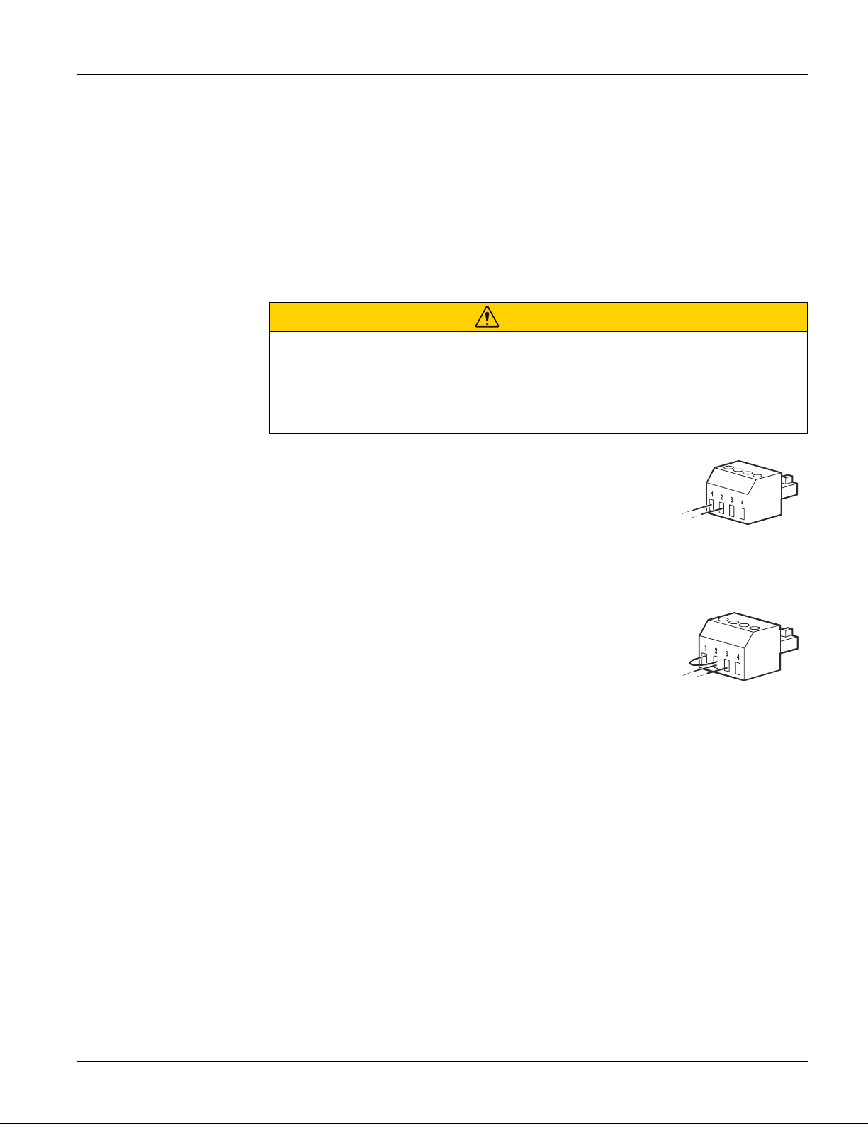
Normally open contacts
1. If the EPO switch or relay contacts are normally open,
insert the wires from the switch or contacts at pins 1 and 2
of the EPO terminal block. Use 16-28 AWG wire.
2. Secure the wires by tightening the screws.
If the contacts are closed, the UPS will turn OFF and power will be removed from the
load.
Normally closed contacts
1. If the EPO switch or relay contacts are normally closed,
insert the wires from the switch or contacts at pins 2 and 3
of the EPO terminal block. Use 16-28 AWG wire.
2. Insert a wire jumper between pins 1 and 2. Secure the
wires by tightening the three screws at positions 1, 2, and 3.
If the contacts are opened, the UPS will turn OFF and power will be removed from the
load.
Note: Pin 1 is the power source for the EPO circuit, it provides a few milliAmps of 24
V power.
If the normally closed (NC) EPO configuration is used, the EPO switch or relay should
be rated for dry circuit applications, the rating should be for low voltage and low
current applications. This normally implies the contacts are gold plated.
The EPO interface is a Safety Extra Low Voltage (SELV) circuit. Connect the EPO
interface only to other SELV circuits. The EPO interface monitors circuits that have no
determined voltage potential. SELV circuits are controlled by a switch or relay properly
isolated from utility power. To avoid damage to the UPS, do not connect the EPO
interface to any circuit other than a SELV circuit.
CAUTION
RISK OF ELECTRIC SHOCK
• Adhere to all local and national electrical codes.
• Wiring should be performed by a qualified electrician.
• Always connect the UPS to a grounded outlet.
Failure to follow these instructions can result in minor or moderate injury.