SU_UM_TME20822_EN.pdf - 第28页
28 Smart-UPS S MTL 22 00/3000 RMI2UC/RMI2UCNC Emergen cy Power Of f EN TME2 08 22 – 08/2 023 Use o ne of the f oll owing cable type s t o connect t he UP S to t he E PO sw i tch. • CL2: Class 2 cable for general u s e. •…
27
Emergency Power Off
Smart-UPS SMTL 2200/3000 RMI2UC/RMI2UCNC
EN TME20822 – 08/2023
Emergency Power Off
Overview
The Emergency Power Off (EPO) option is a safety feature that will immediately shut
off power to all connected equipment. When the EPO button is pushed, all connected
equipment will immediately turn off and will not switch to battery power.
Connect each UPS to the EPO switch. In configurations where multiple units are
connected in parallel, each UPS must be connected to the EPO switch.
The UPS must be restarted for power to return to connected equipment. Press the
ON/OFF button on the front panel of the UPS.
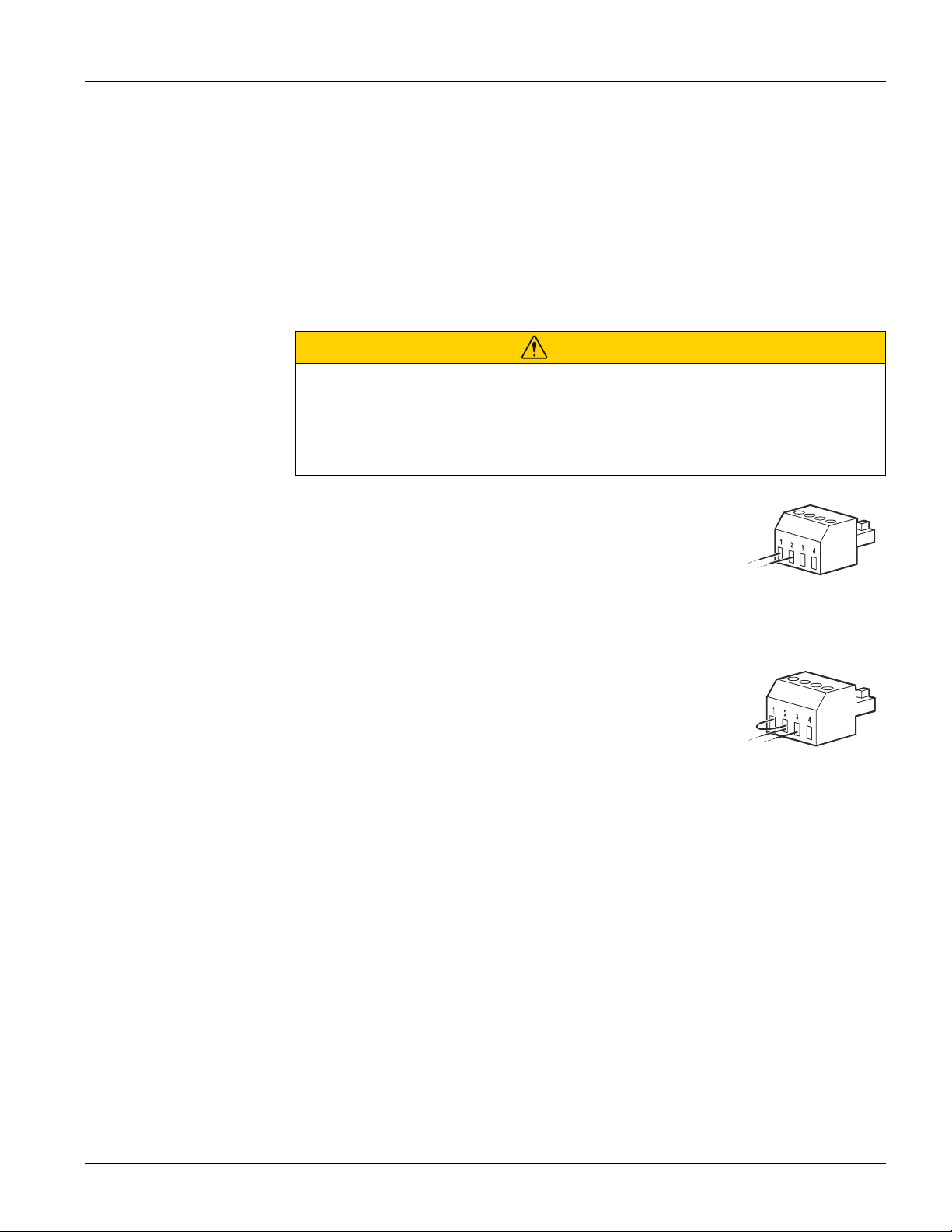
Normally open contacts
1. If the EPO switch or relay contacts are normally open,
insert the wires from the switch or contacts at pins 1 and 2
of the EPO terminal block. Use 16-28 AWG wire.
2. Secure the wires by tightening the screws.
If the contacts are closed, the UPS will turn OFF and power will be removed from the
load.
Normally closed contacts
1. If the EPO switch or relay contacts are normally closed,
insert the wires from the switch or contacts at pins 2 and 3
of the EPO terminal block. Use 16-28 AWG wire.
2. Insert a wire jumper between pins 1 and 2. Secure the
wires by tightening the three screws at positions 1, 2, and 3.
If the contacts are opened, the UPS will turn OFF and power will be removed from the
load.
Note: Pin 1 is the power source for the EPO circuit, it provides a few milliAmps of 24
V power.
If the normally closed (NC) EPO configuration is used, the EPO switch or relay should
be rated for dry circuit applications, the rating should be for low voltage and low
current applications. This normally implies the contacts are gold plated.
The EPO interface is a Safety Extra Low Voltage (SELV) circuit. Connect the EPO
interface only to other SELV circuits. The EPO interface monitors circuits that have no
determined voltage potential. SELV circuits are controlled by a switch or relay properly
isolated from utility power. To avoid damage to the UPS, do not connect the EPO
interface to any circuit other than a SELV circuit.
CAUTION
RISK OF ELECTRIC SHOCK
• Adhere to all local and national electrical codes.
• Wiring should be performed by a qualified electrician.
• Always connect the UPS to a grounded outlet.
Failure to follow these instructions can result in minor or moderate injury.

28
Smart-UPS SMTL 2200/3000 RMI2UC/RMI2UCNC
Emergency Power Off
EN TME20822 – 08/2023
Use one of the following cable types to connect the UPS to the EPO switch.
• CL2: Class 2 cable for general use.
• CL2P: Plenum cable for use in ducts, plenums, and other spaces used for
environmental air.
• CL2R: Riser cable for use in a vertical run in a floor-to-floor shaft.
• CLEX: Limited use cable for use in dwellings and for use in raceways.
• Installation in Canada: Use only CSA certified, type ELC, (extra low voltage control
cable).
• Installation in countries other than Canada and the USA: Use standard low voltage
cable in accordance with national and local regulations.

29
Troubleshooting
Smart-UPS SMTL 2200/3000 RMI2UC/RMI2UCNC
EN TME20822 – 08/2023
Troubleshooting
Problem and Possible Cause Solution
The UPS will not turn on or there is no output.
The unit has not been turned on. Press the
UPS ON/OFF key once to turn on the
UPS.
The UPS is not connected to AC
power.
Be sure the power cable is securely connected
to the unit and to the AC power supply.
The input circuit breaker has
tripped.
Reduce the load on the UPS. Disconnect
nonessential equipment and reset the circuit
breaker.
The unit shows very low or no
input AC voltage.
Check the AC power supply to the UPS by
plugging in a table lamp. If the light is very dim,
check the AC voltage.
The battery connector plug is not
securely connected.
Be sure that all battery connections are secure.
There is an internal UPS error
detected.
Do not attempt to use the UPS. Unplug the UPS
and have it serviced immediately.
The UPS is operating on battery, while connected to input AC power.
The input circuit breaker has
tripped.
Reduce the load on the UPS. Disconnect
nonessential equipment and reset the circuit
breaker.
There is very high, very low, or
distorted input line voltage.
Move the UPS to a different outlet on a different
circuit. Test the input voltage with the AC
voltage display. If acceptable to the connected
equipment, reduce the UPS sensitivity.
UPS is emitting intermittent beeps.
The UPS is operating normally. None. The UPS is helping protect the connected
equipment.
UPS does not provide expected backup time.
The UPS battery is weak due to a
recent power outage or is near the
end of its service life.
Charge the battery. Batteries require recharging
after extended outages and wear out faster
when put into service often or when operated at
elevated temperatures. If the battery is near the
end of its service life, consider replacing the
battery even if the replace battery indicator has
not illuminated.
The UPS is experiencing an
overload condition.
Check the UPS load display. Unplug
unnecessary equipment, such as printers.
Display interface LEDs flash sequentially.
The UPS has been shut down
remotely through software or an
optional accessory card.
None. The UPS will restart automatically when
AC power is restored.
The Error LED is illuminated. The UPS displays an error message and emits a
constant beeping sound.
Internal UPS error detected. Do not attempt to use the UPS. Turn the UPS off
and have it serviced immediately.
The Replace Battery icon is illuminated and the UPS beeps for one minute
every five hours.
The battery has a weak charge. Allow the battery to recharge for at least four
hours. Then, perform a self-test. If the problem
persists after recharging, replace the battery.