Infinity EX High Throughput Conveyor Module.pdf - 第10页
INFINITY EX HIGH THROUG HPUT CONVEY OR MODULE MECHANICAL DETA IL 16.1 0 Technical Reference Manual C hapter Issue 1 Aug 02 Figure 16-7 M27 Controller Fast/Normal Mode For a con veyor to operate in fast transfer mode, bot…
INFINITY
EX
HIGH THROUGHPUT CONVEYOR MODULE
MECHANICAL DETAIL
Chapter Issue 1 Aug 02 Technical Reference Manual 16.9
High Throughput
Conveyor
Controller (M27)
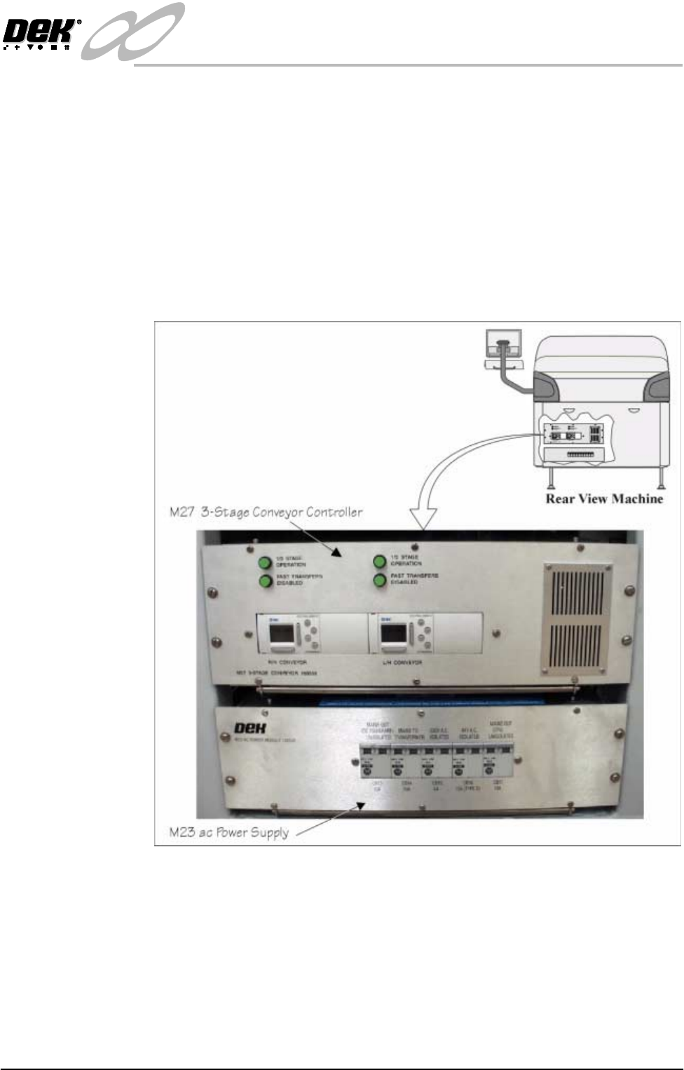
The 3-Stage conveyor controller (M27) enclosure is located at the rear of the
machine above the ac power supply module (M23).
The M27 consists of a Programmable Logic Controller (PLC) for each auxiliary
conveyor. Above each PLC are the switches for selecting between 3-Stage/
single stage and fast/normal mode (Stage Conveyor Controller (M27) figure
refers).
On machine initialisation, each auxiliary conveyor PLC needs to detect the
machine ‘System Power’ and an initial ‘Downline Available’ signals before the
system starts operating. If the machine is being run in a stand-alone environ-
ment, the ‘Downline Available’ signal from the downline machine can be
mimicked by shorting pins 1 & 2 of loom Pt No 160645 to the downline machine.
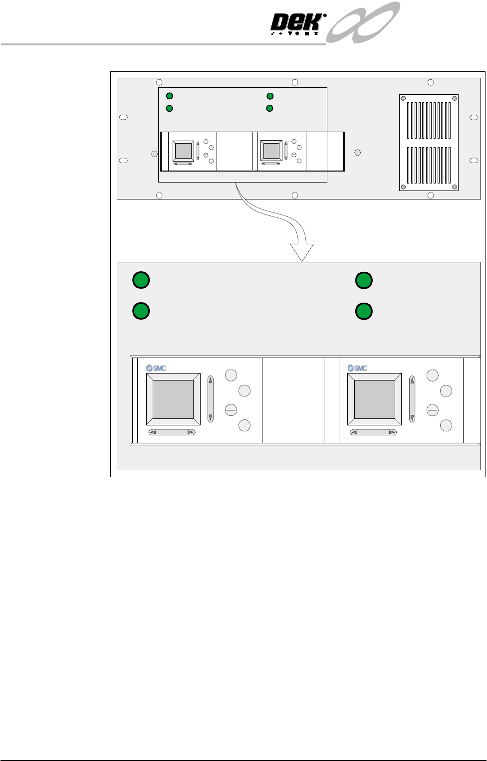
Figure 16-6 M27 Enclosure Overview
3-Stage/Single Stage
Mode
For three stage mode, both 1/3 Stage Operation buttons must be OFF (LED
extinguished). The LCD screen on the PLC displays ‘3 Stage’ on the top line.
For single stage mode, both 1/3 Stage Operation buttons must be ON (LED lit).
The LCD screen on the PLC displays ‘1 Stage’ on the top line.
INFINITY
EX
HIGH THROUGHPUT CONVEYOR MODULE
MECHANICAL DETAIL
16.10 Technical Reference Manual Chapter Issue 1 Aug 02
Figure 16-7 M27 Controller
Fast/Normal Mode For a conveyor to operate in fast transfer mode, both Fast Transfers Disabled
buttons must be OFF (LED extinguished). The LCD screen on the PLC displays
‘Fst.Trans.’ on the bottom line for 5 seconds on power up or when the button is
switched to OFF.
For a conveyor to operate in normal transfer mode, both Fast Transfers Disabled
buttons must be ON (LED lit). Normal transfer mode is not displayed on the
PLC.
1/3 STAGE
OPERATION
1/3 STAGE
OPERATION
FAST TRANSFERS
DISABLED
FAST TRANSFERS
DISABLED
R/H CONVEYOR L/H CONVEYOR
+
ESC
OK
+
OK
ESC
1/3 STAGE
OPERATION
1/3 STAGE
OPERATION
FAST TRANSFERS
DISABLED
FAST TRANSFERS
DISABLED
M27 3-STAGE CONVEYOR 160558
LANE A (R/H) LANE A (L/H)
+
OK
ESC
+
OK
ESC
INFINITY
EX
HIGH THROUGHPUT CONVEYOR MODULE
MECHANICAL DETAIL
Chapter Issue 1 Aug 02 Technical Reference Manual 16.11
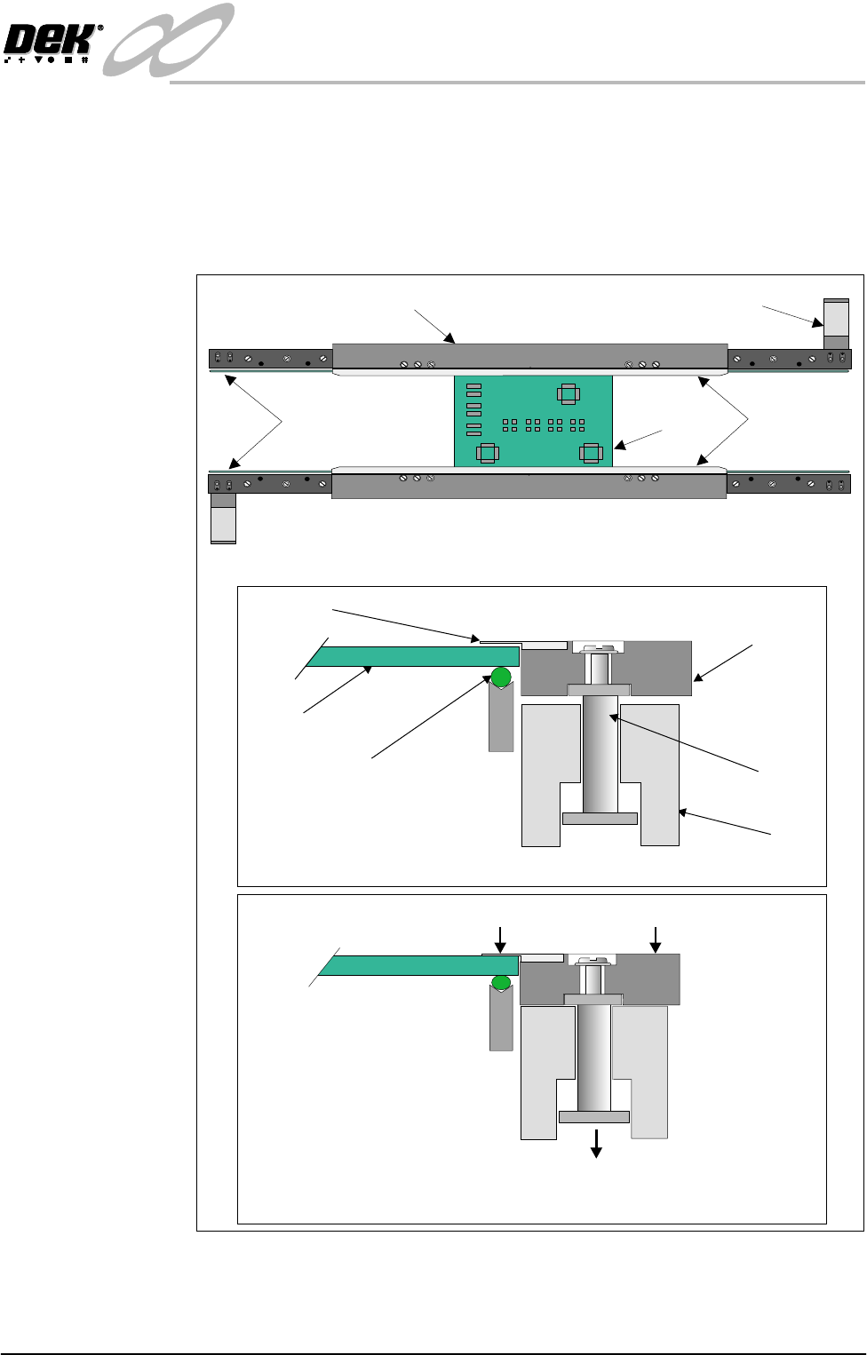
Board Clamps A board clamping arrangement is utilized to secure the board during the print
process and to minimize board distortion. A pneumatically operated piston, (via
a 24V switched solenoid 16SOL10 from the machine controller), lowers the
board clamp and foil, trapping the board on the transport belts. On completion
of the print stroke the board is released by activation of the pneumatic solenoid.
An in-line pneumatic exhaust ensures quick release of the board clamps.
Figure 16-8 Board Clamping Arrangement
Board Snugger
Assembly
The board snugger assembly is an alternative option to the standard board clamp
arrangement. This feature is utilized when there is a requirement to print close
Transport Belt
Rail
Piston
Metal Foil
Board Clamp
Board
Pneumatic Piston Driven Downwards
Board Trapped Between Foil and Transport Belt
Board Clamp and Foil Lowered
WARNING SHARP EDGE
PATENT No 5157438
WARNING SHARP EDGE
PATENT No 5157438
Transport Belt MotorBoard Clamp
Transport Belts
Metal Foils
Board
Plan View of Print Station Conveyor
Board Free on Transport Belt