Infinity EX High Throughput Conveyor Module.pdf - 第25页
INFINITY EX HIGH THROUG HPUT CONVE YOR MODULE ADJUS TMENT S AND SET TINGS Chapter Issu e 1 Aug 02 Technical Reference Manual 16.25 2. Remov e the sensor mounti ng scre ws from the sensor mounting bracket and adjust the p…
INFINITY
EX
HIGH THROUGHPUT CONVEYOR MODULE
ADJUSTMENTS AND SETTINGS
16.24 Technical Reference Manual Chapter Issue 1 Aug 02
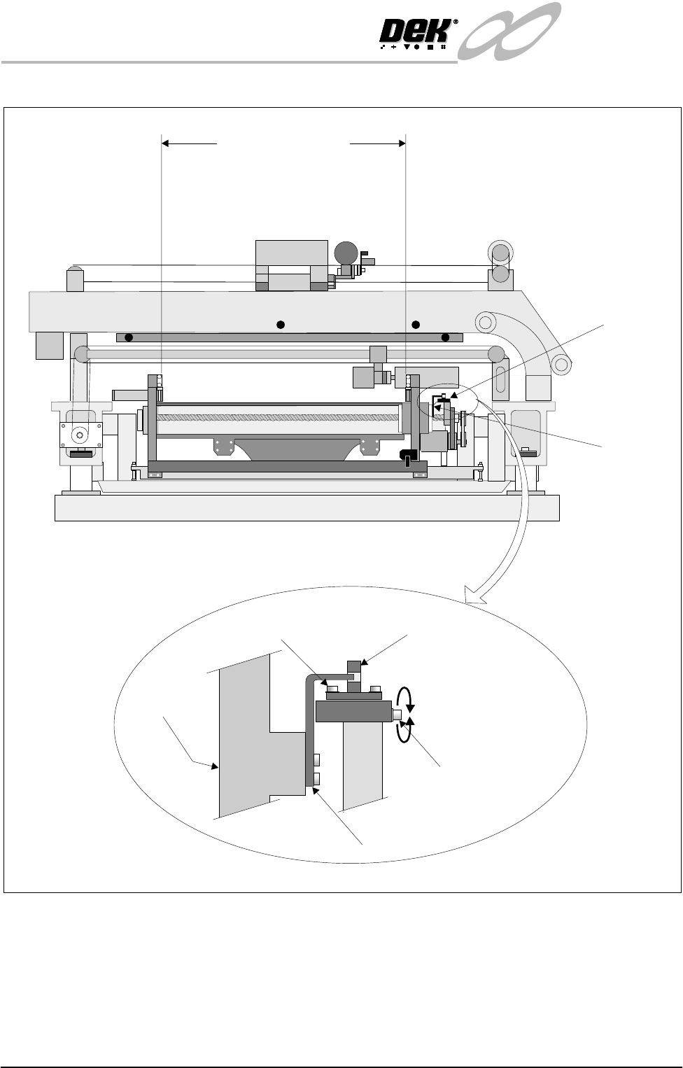
Figure 16-16 Rail Width Board Sensor Setting
Auxiliary Conveyor Sensors
Positional
Adjustment
If heavy boards are being printed and causing damage to the conveyor board
stops, adjustment of the position of the sensor can be carried out to minimise this
effect. To adjust the position of the sensor carry out the following:
1. Power down the machine.
Rail Home
Sensor
Rail Home
Opto Flag
(home vane)
Betweeninsideedgesof rails
View on Right Hand Side of Machine
508.5mm - 508.7 mm
Adjustable Through
Beam Opto Sensor
Home Sensor Adjustment
Screw (0.5mm Pitched
Thread)
Rear Rail
Opto Flag
Sensor Forward Securing Screw
Enlarged View of Rail Home Position Sensor
INFINITY
EX
HIGH THROUGHPUT CONVEYOR MODULE
ADJUSTMENTS AND SETTINGS
Chapter Issue 1 Aug 02 Technical Reference Manual 16.25
2. Remove the sensor mounting screws from the sensor mounting bracket and
adjust the position of the sensor to align with another set of mounting holes
on the mounting bracket.
3. Secure the sensor in position with the two mounting screws.
4. Power up and run the machine, checking for correct operation of the sensor.
5. If coarse adjustment of the sensor position is required, this can be achieved
adjusting the position of the sensor mounting bracket by use of the inboard
sensor bracket mounting holes.
Sensitivity
Adjustment
The auxiliary conveyors are a diffuse sensor type. The sensor switching thresh-
old can be adjusted by means of a sensitivity control switch mounted on the face
of the sensor. This ensures that when a board is fed into the machine (via
transport belts) the sensor output switches to ON.
To achieve an optimum setting carry out the following:
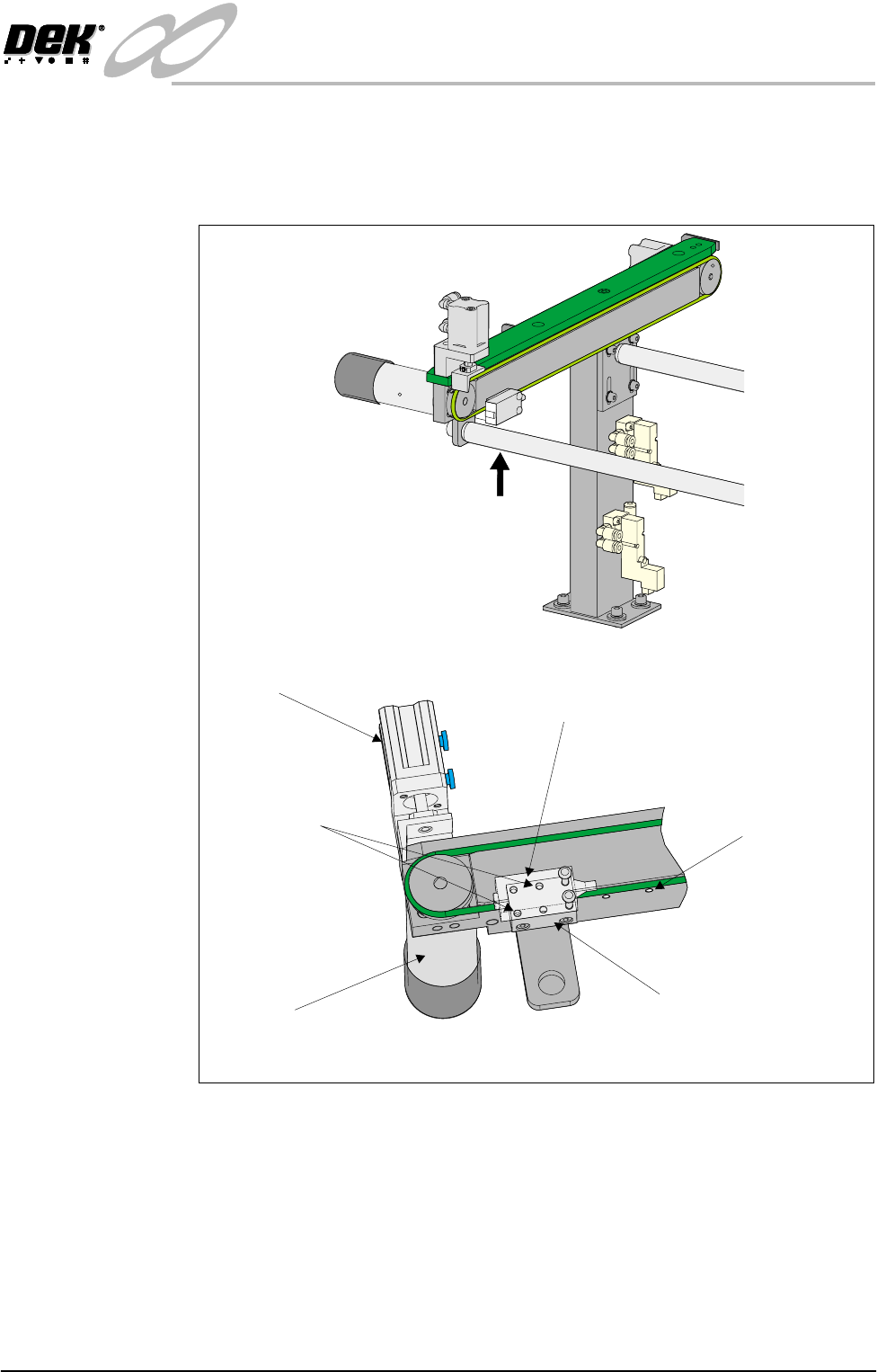
Rear View on Auxiliary Conveyor
A
View on Arrow ‘A’
Conveyor Board Stop
Transport Belt Motor
Sensor
Sensor Mounting Holes
(in 6 positions)
Sensor Mounting Bracket
Bracket Mounting Holes
(in 4 positions)
INFINITY
EX
HIGH THROUGHPUT CONVEYOR MODULE
ADJUSTMENTS AND SETTINGS
16.26 Technical Reference Manual Chapter Issue 1 Aug 02
1. Place a board on the rails covering the sensor.
2. Turn the sensitivity control on the face of the sensor fully anti-clockwise,
ensure the green and red LED is extinguished.
3. Re-adjust the sensitivity control clockwise until both LEDs illuminate.
Continue rotating the sensitivity control one more graduration clockwise.
4. Remove the board from the rails and confirm that both LEDs are extin-
guished.
5. Remove the board. Repeat Step 1 and confirm that both LEDs illuminate.
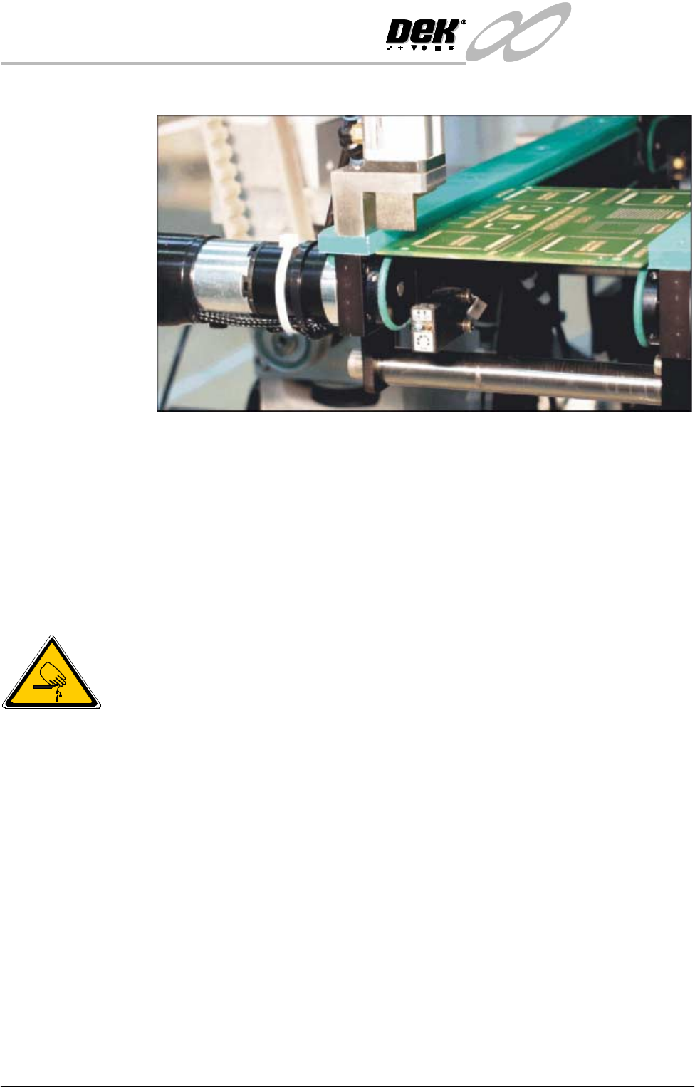
Board at Left/Right Optos
WARNING
BOARD CLAMPS. EXTREME CARE MUST BE EXERCISED WHEN
WORKING IN THE TOOLING AREA OF THE MACHINE TO AVOID
INJURY. THE FOILS ON THE FRONT AND REAR BOARD CLAMPS
ARE VERY SHARP.
Positional
Adjustment
If heavy boards are being printed and causing damage to the conveyor board
stops, adjustment of the position of the sensor can be carried out to minimise this
effect. To adjust the position of the sensor carry out the following:
1. Power down the machine.
2. Loosen sensor mounting bracket bolts. Adjust the position of the mounting