Infinity EX High Throughput Conveyor Module.pdf - 第31页
INFINITY EX HIGH THROUG HPUT CONVE YOR MODULE ADJUS TMENT S AND SET TINGS Chapter Issu e 1 Aug 02 Technical Reference Manual 16.31 4. Using a suitable vernier calli per , at these points, check the rear ra il to front ra…
INFINITY
EX
HIGH THROUGHPUT CONVEYOR MODULE
ADJUSTMENTS AND SETTINGS
16.30 Technical Reference Manual Chapter Issue 1 Aug 02
8. Remove the D.T.I.
9. Carry out either of the following:
a. Refit the camera (see Camera and Vision Systems Module Chapter, Cam-
era Refitment).
b. Remove the spare camera bearing from camera rail.
10.Switch on the machine, remove the head prop and lower the head. Initialize,
carry out the Home Position Rail Width Check and Camera Reference
Position (see Rail System Module Chapter and Camera and Vision Systems
Module Chapter).
Print Station Rear Rail Parallelism
WARNING
BOARD CLAMPS. EXTREME CARE MUST BE EXERCISED WHEN
WORKING IN THE TOOLING AREA OF THE MACHINE TO AVOID
INJURY. THE FOILS ON THE FRONT AND REAR BOARD CLAMPS
ARE VERY SHARP.
NOTE
Ensure Camera X Axis and Front Rail Parallelism (see Camera and Vision
Systems Module Chapter and Rail System Module Chapter) has been carried out
prior to commencing this procedure.
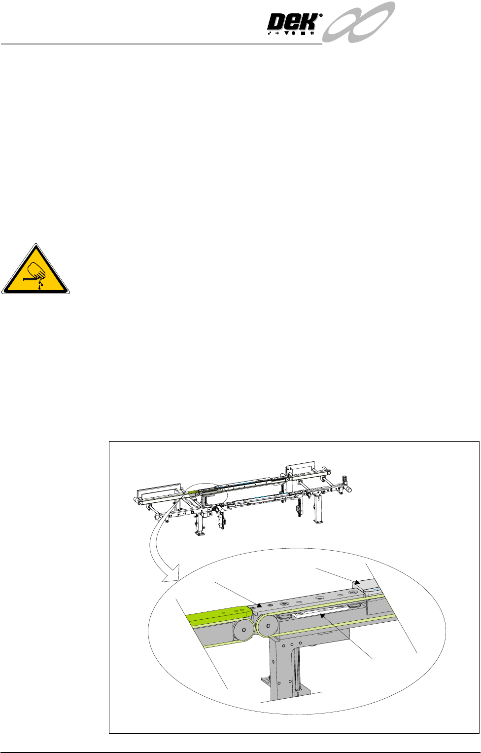
1. In Rail System Diagnostics, select Adjust and alter board width to 250mm.
2. Select Drive Rail to Board Width. The rails are driven to the board width
selected.
3. Locate all four mid rail tooling steps, two on each rail.
Mid Rail Tooling Step
Board Clamp
Mid Rail
View on Front Face of Print Station
INFINITY
EX
HIGH THROUGHPUT CONVEYOR MODULE
ADJUSTMENTS AND SETTINGS
Chapter Issue 1 Aug 02 Technical Reference Manual 16.31
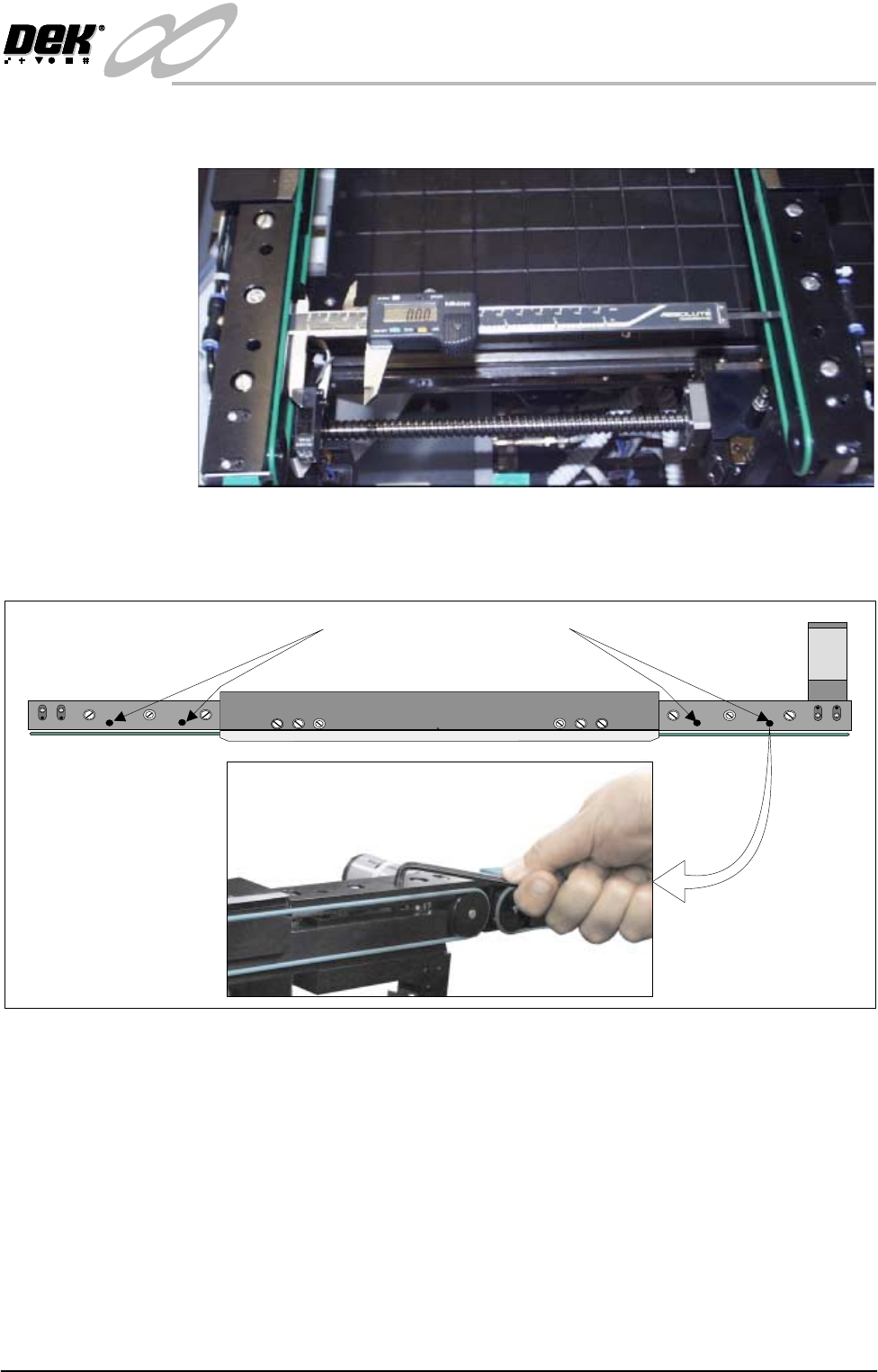
4. Using a suitable vernier calliper, at these points, check the rear rail to front
rail parallelism to within ±0.2mm.
5. If adjustment is necessary, using an Allen key, slacken the four rail securing
bolts and adjust the rear rail as required. Tighten the bolts, re-check the
parallelism.
6. On completion, carry out Home Position Rail Width check.
Auxiliary Rail to
Print Station Gap
To check and if required adjust the gaps between the print station rail and the
auxiliary conveyors carry out the following procedure:
NOTE
To carry out this procedure on the front rail, the conveyor board stops must be
removed prior to and refitted on completion of this procedure.
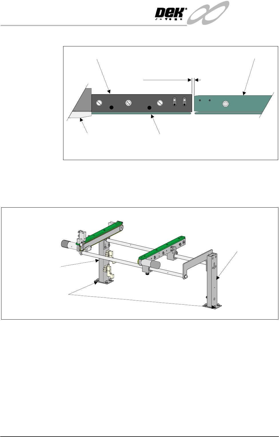
1. Using feeler gauges or a 3mm allen key, ensure that the gap between the print
WARNING SHARP EDGE
PATENT No 5157438
Print Station Rail Securing Bolts
INFINITY
EX
HIGH THROUGHPUT CONVEYOR MODULE
ADJUSTMENTS AND SETTINGS
16.32 Technical Reference Manual Chapter Issue 1 Aug 02
station and the auxiliary conveyors (in four positions) is 3.0 ± 0.5mm.
2. If adjustment is required, carry out the following:
a. Right hand conveyor - loosen the eight auxiliary conveyor rail support
securing bolts (four bolts on each support) that secure the auxiliary
conveyor to the machine lower frame.
b. Left hand conveyor - loosen the eight auxiliary conveyor left hand frame
Board Clamp
Board Transport Rail
Auxiliary Conveyor
Print Station
Plan View on Print Station and Auxiliary Rails
5157438
3.0mm +/- 0.5mm
Rear View of Right Auxiliary Conveyor
Front Auxiliary Conveyor
Rail Support
Rear Auxiliary Conveyor
Rail Support
Rail Support to Main Frame
Bolts (4 bolts in 2 positions)