Infinity EX High Throughput Conveyor Module.pdf - 第42页
INFINITY EX HIGH THROUG HPUT CONVEY OR MODULE ADJUS TMEN TS AND SE TTINGS 16.4 2 Technical Reference Manual C hapter Issue 1 Aug 02 Quick Fit Board Cl amp Set ting W ARNING BO ARD CLAMPS. EXTREME CARE MUST BE EXERCISE D …
INFINITY
EX
HIGH THROUGHPUT CONVEYOR MODULE
ADJUSTMENTS AND SETTINGS
Chapter Issue 1 Aug 02 Technical Reference Manual 16.41
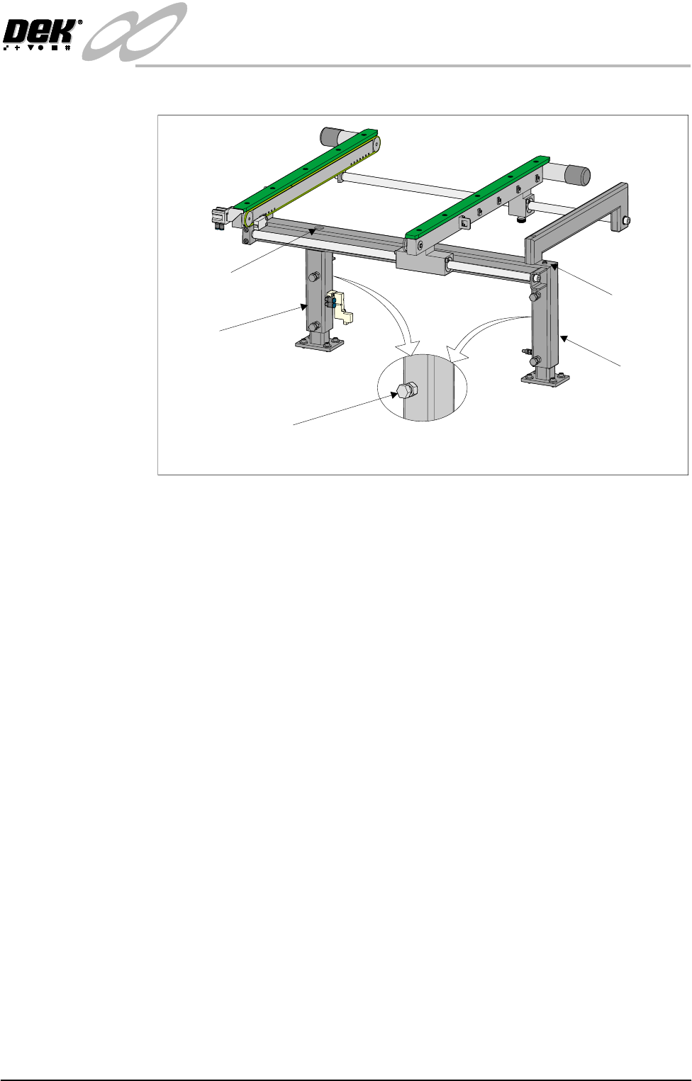
both uprights.
9. Re-tighten the bolts loosened in Step 7 and repeat the check.
10.If adjustment has occurred, carry out Auxiliary Conveyor Levelling check.
Rear View of Left Hand Auxiliary Conveyor
Bolt C on Outer Face
Of Conveyor Frame Uprights
Rear Upright of
Conveyor Frame
Front Upright of
Conveyor Frame
Height Adjustment
Grub Screw
Height Adjustment
Grub Screw
INFINITY
EX
HIGH THROUGHPUT CONVEYOR MODULE
ADJUSTMENTS AND SETTINGS
16.42 Technical Reference Manual Chapter Issue 1 Aug 02
Quick Fit Board Clamp Setting
WARNING
BOARD CLAMPS. EXTREME CARE MUST BE EXERCISED WHEN
WORKING IN THE TOOLING AREA OF THE MACHINE TO AVOID
INJURY. THE FOILS ON THE FRONT AND REAR BOARD CLAMPS
ARE VERY SHARP.
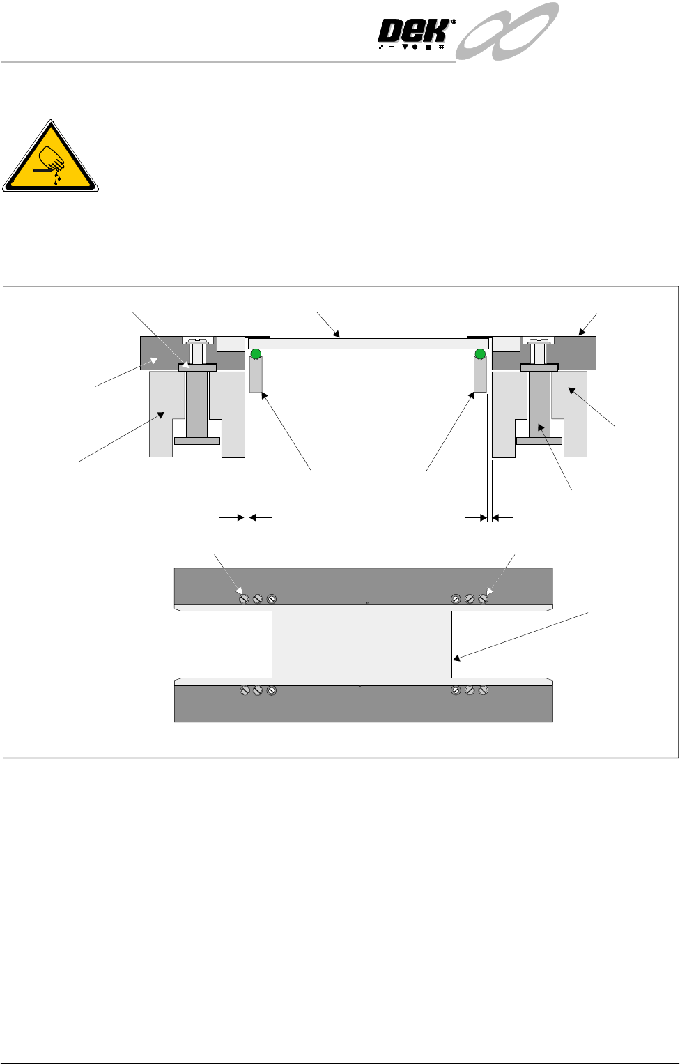
1. Check that a gap between the front board clamp and the transport belt is set
between 0.1mm - 0.15mm. Ensure that the front board clamp is parallel to
the front transport belt.
2. If adjustment is necessary, slacken screw A (2 positions) and adjust. Tighten
screw A (2 positions) on completion.
3. Repeat Steps 1 and 2 for the rear board clamp.
4. Gently move the rear rail in by hand enabling the setting plate (140403) to
be moved along the transport rails until it sits along the entire length of the
board clamp. Gently move the rear rail in by hand until the front and rear
clamps grip the setting plate.
5. Using a 0.05mm feeler gauge check along the whole length of both clamps
for gaps. If the feeler enters any gaps, slacken screws A on the rear board
clamp and adjust. Tighten screws A on completion.
6. If any adjustment is carried out, ensure that gaps set in Steps 1 and 2 are
maintained.
7. Check for correct operation of the board clamps after any adjustment is
made.
WARNING SHARP EDGE
WARNING SHARP EDGE
PATENT No.5157438
PATENT No.5157438
Board Clamp
Setting Plate
A
A
Board Clamp Mechanism
Front Fixed Rail
Transport Belt Guides
0.1mm - 0.15mm
0.1mm - 0.15mm
Board Clamp Mounting Plate
Board Clamp Setting Plate
Front Board Clamp
Rear Board Clamp
Moving Rail
Board Clamp Guide
INFINITY
EX
HIGH THROUGHPUT CONVEYOR MODULE
ADJUSTMENTS AND SETTINGS
Chapter Issue 1 Aug 02 Technical Reference Manual 16.43
Quick Fit Board Clamp Foil Replacement
WARNING
BOARD CLAMPS. EXTREME CARE MUST BE EXERCISED WHEN
WORKING IN THE TOOLING AREA OF THE MACHINE TO AVOID
INJURY. THE FOILS ON THE FRONT AND REAR BOARD CLAMPS
ARE VERY SHARP.
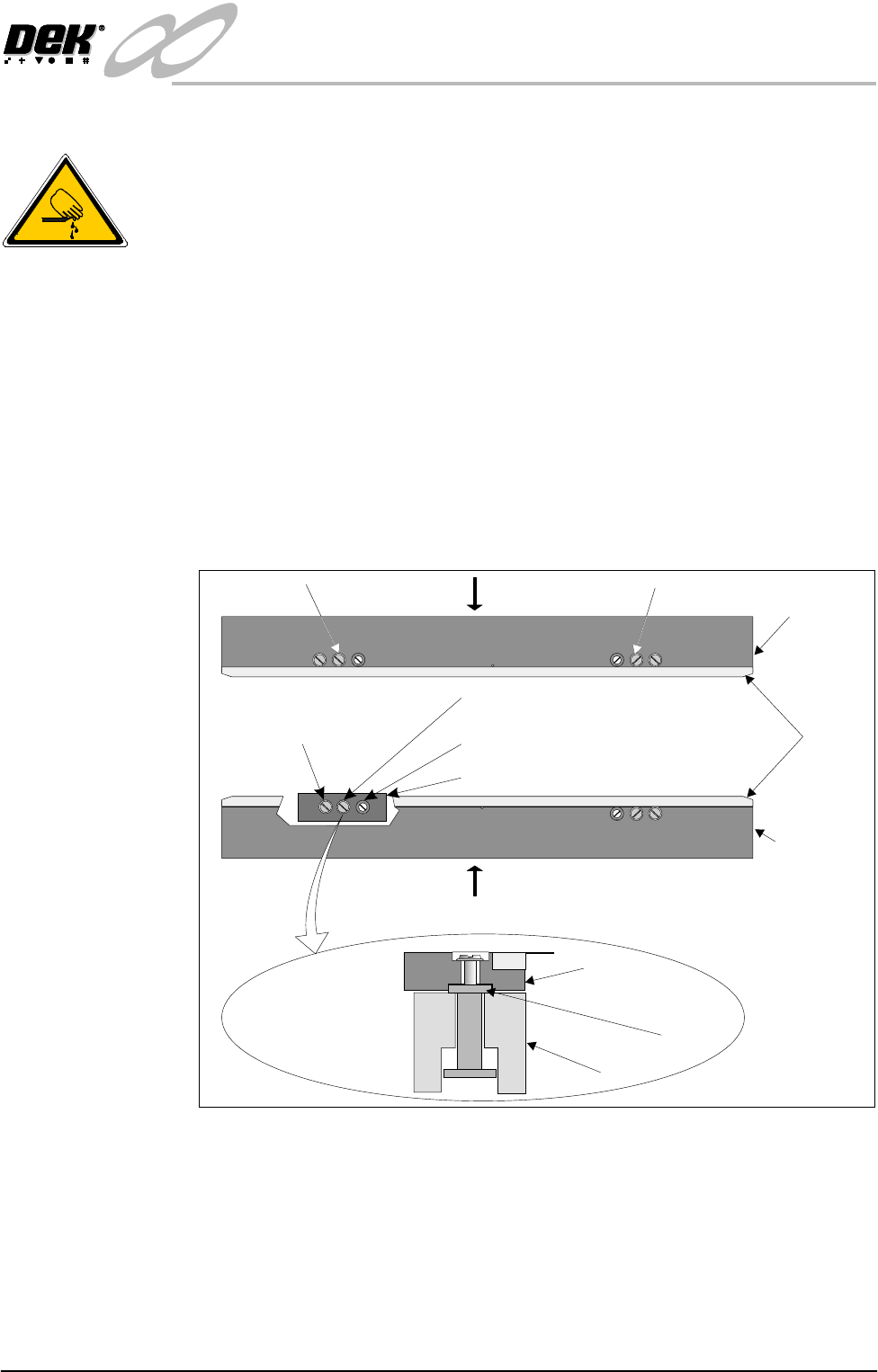
1. Remove screws C and lift off the board clamp (see Note 1). Retain the two
screws.
2. Remove the eight M2.5 x 6mm pan headed slotted screws securing the foil
to the board clamp. Discard the foil and retain the eight screws.
3. Fit the new foil with the screws removed in Step 2.
4. Place the board clamp with new foil into it’s original position.
5. Slide the board clamp in the direction of arrow A for the rear board clamp
and arrow B for the front board clamp. This ensures the board clamp butts
up against the outside face of the board clamp mounting plate.
6. Secure the board clamp with the screws removed in Step 1.
NOTE
1. Due to build tolerances the board clamps must be refitted to the same
position.
2. The board clamp setting up procedure is not required after board clamp
foil replacement.
WARNING SHARP EDGE
WARNING SHARP EDGE
PATENT No.5157438
PATENT No.5157438
C C
B
A
Rear Board
Clamp
Front Board
Clamp
Foils
Piston Screw
Carrier
Carrier Securing Screw
Cutaway showing a Carrier
Guide Locking Screw
Rail
Carrier
Board Clamp
Side View of Carrier
Plan View on Print Station showing Carrier Adjustment