Infinity EX High Throughput Conveyor Module.pdf - 第45页
INFINITY EX HIGH THROUG HPUT CONVE YOR MODULE ADJUS TMENT S AND SET TINGS Chapter Issu e 1 Aug 02 Technical Reference Manual 16.45 Snugger Clamp Setting (Height ) The procedure for setting up the snugger height is as fol…
INFINITY
EX
HIGH THROUGHPUT CONVEYOR MODULE
ADJUSTMENTS AND SETTINGS
16.44 Technical Reference Manual Chapter Issue 1 Aug 02
Snugger Clamp
Setting
(Parallelism)
The adjustable snugger plate, rear rail guide and fixed snugger plate are all
interchangeable with similar units to facilitate differences in board thicknesses
(0.8mm, 1.0mm and 1.6mm).
The following checks and adjustment settings for the snugger clamp is applica-
ble to all three size configurations.
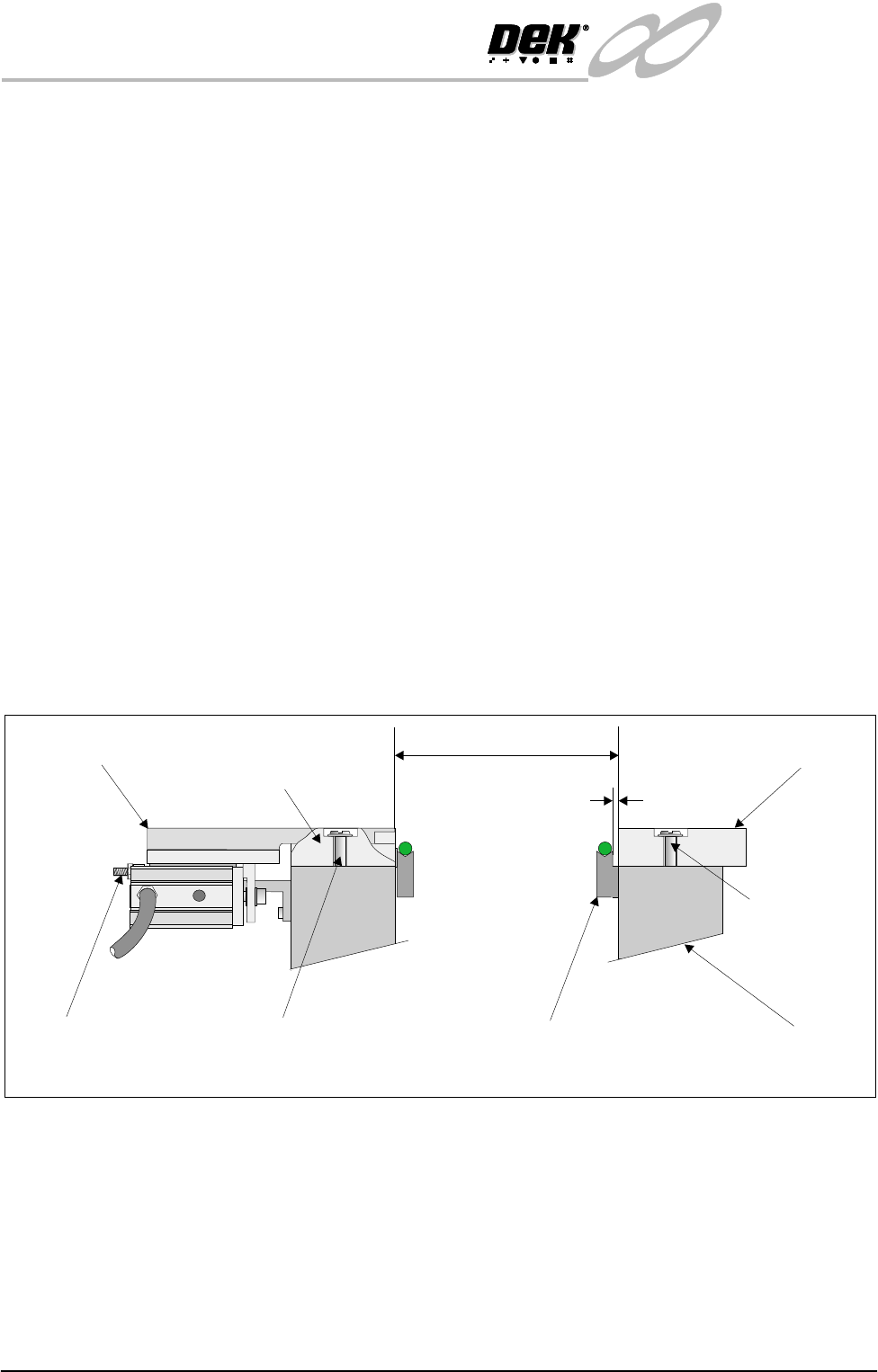
The procedure for setting up snugger parallelism is as follows:
1. Using a 0.10mm feeler gauge check that the gap between the fixed snugger
plate and transport belt guide is set between 0.10mm - 0.15mm. Ensure that
parallelism is achieved along the full length of the snugger plate.
2. If adjustment is necessary. Slacken fixed snugger plate securing screws (3
in number) and adjust.
3. Using a vernier gauge measure the distance between the fixed snugger plate
and rear rail guide, gently move the rear rail forward until a gap of 250mm
±0.1mm is achieved. Ensure that parallelism is maintained along the full
length.
4. If adjustment is necessary. Slacken rear rail guide securing screws (3 in
number) and adjust.
5. Ensure that parallelism is achieved along the rear rail guide and adjustable
snugger plate. This is achieved by using a vernier gauge and checking that
the rear rail guide/adjustable snugger plate is the same distance to the front
snugger plate. Adjust the two stop mount bolts to move the snugger plate if
required.
Transport Belt Guide
Fixed Snugger Plate
Fixed Rail
0.1mm - 0.15mm
250mm +/- 0.1mm
Securing Screws
(3 in Number)
Securing Screws (3 in Number)
Stop Mount Bolts
(2 in Number)
Adjustable Snugger Plate
Rear Rail Guide
(Cutaway)
Side View showing Snugger Clamp Detail (Parallelism)
INFINITY
EX
HIGH THROUGHPUT CONVEYOR MODULE
ADJUSTMENTS AND SETTINGS
Chapter Issue 1 Aug 02 Technical Reference Manual 16.45
Snugger Clamp
Setting (Height)
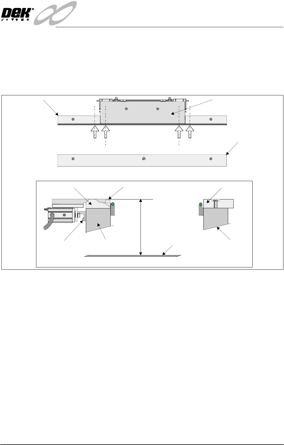
The procedure for setting up the snugger height is as follows:
1. Before setting snugger height, check the rail to table height (Rising Table
Chapter).
2. Place a straight edge on the top surface of the rear rail guide (Position A1 on
figure below refers). Using a depth gauge indicator measure the distance
from the top of the rising table to the top of the rear rail guide.
3. Carry out same operation at Position A2.
4. Check that the dimensions in Steps 2 and 3 are the same (to within 0.2mm).
If necessary adjust by slackening snugger support bracket securing screws.
Do not fully re-tighten screws at this point.
5. Carry out identical checks at other end of adjustable snugger plate (Position
B1 and B2). On completion of check/adjustments fully re-tighten bracket
securing screws.
NOTE
If adjustments are made ensure that a gap of 250mm is maintained as laid
out in Parallelism setting up.
6. On completion of setting up ensure that the board is free to move along the
transport rail without jamming.
7. Pneumatically operate the snugger clamp with a board fitted. Ensure that the
board is gripped evenly along its entire length.
Adjustable Snugger Plate
Fixed Snugger Plate
Plan View Print Station
Rear Rail Guide
I.O
Position A1
Position A2
Position B2
Position B1
Snugger Height Adjustment
Fixed Snugger Plate
Rear Rail Guide (Cutaway)
Fixed RailRear Rail (Moving)
Adjustable Snugger Plate
Rising Table
Dimension at Positions
A1/A2 and B1/B2
Snugger Support
Bracket Screws
(3 in Number)

INFINITY
EX
HIGH THROUGHPUT CONVEYOR MODULE
ADJUSTMENTS AND SETTINGS
16.46 Technical Reference Manual Chapter Issue 1 Aug 02
Home Position Rail
Width Check
1. In Diagnostics, select Rail System and Select Module.
2. Select Home Rail Width and Run Diagnost.
3. Select Adjust and set board width to 250mm (Carrier Handling Option -
300mm).
4. Select Drive Rail to Board Width.
5. Select Run Diagnost.
6. Check that the board clamp width is between 250.35mm - 250.55mm
(Carrier Handling Option - 300.35mm - 300.45mm).
7. Check that the mid rail width is between 250.35mm - 250.65mm (Carrier
Handling Option - 300.35mm - 300.55mm).
8. Check that the rail end green insert width is between 250.35mm - 250.85mm
(Carrier Handling Option - 300.35mm - 300.55mm).
NOTE
If any of the rail widths are out of tolerance do not adjust the rails, adjust the
position of the rail home position sensor and recheck.
9. Using a suitable test board, with the rail width programmed to the board size,
select Cycle Board on Belts.
10.Select Run and ensure the board runs through the entire length of the rail
system for 10 complete cycles, without jamming or excessive clicking of the
board edges.
NOTE
If any jamming occurs investigate the position of the board/snugger clamps, mid
rails and the green inserts at the rail ends before repeating the check.