Infinity EX High Throughput Conveyor Module.pdf - 第48页
INFINITY EX HIGH THROUG HPUT CONVEY OR MODULE ADJUS TMEN TS AND SE TTINGS 16.4 8 Technical Reference Manual C hapter Issue 1 Aug 02 con v e yor rail. 6. Ref it the mounting bracket to left hand con v eyor front rail usin…
INFINITY
EX
HIGH THROUGHPUT CONVEYOR MODULE
ADJUSTMENTS AND SETTINGS
Chapter Issue 1 Aug 02 Technical Reference Manual 16.47
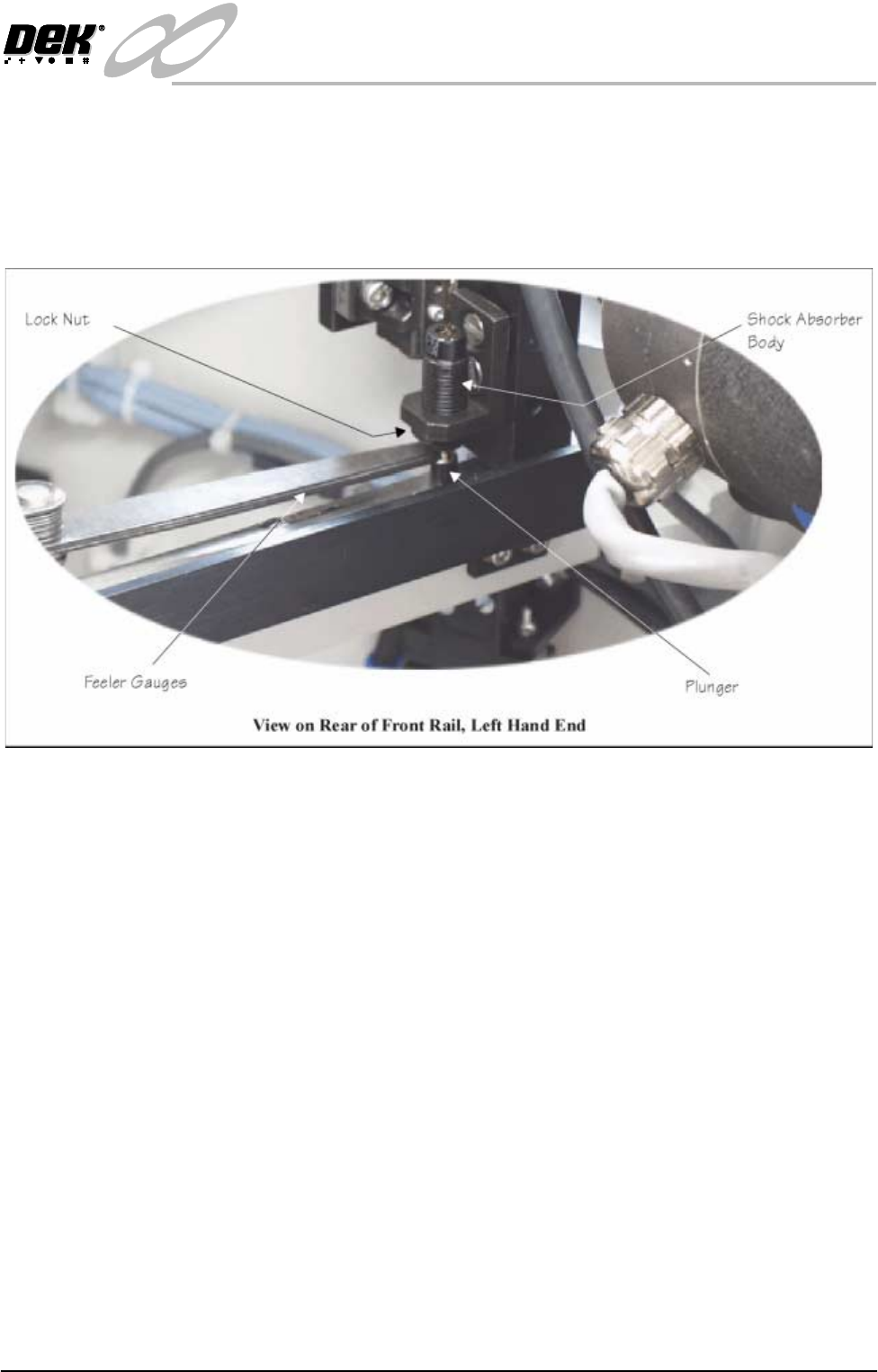
Rail Shock
Absorber Setting
1. Ensure the machine is powered down.
2. Using feeler gauges, check that a gap of 2.5mm - 3mm exists between the
top of the plunger and the shock absorber body. Alternatively use a 2.5mm
and 3mm allen key as a Go, No Go Gauge.
3. Repeat Step 2 for the three other rail shock absorbers.
4. If adjustment is necessary, slacken the lock nut.
5. Rotate the shock absorber body as required, clockwise to reduce the gap,
anti-clockwise to increase the gap.
6. Check the gap is between 2.5mm - 3mm.
7. Repeat Steps 5 and 6 until the correct dimension is achieved
8. Tighten the lock nut.
9. Recheck the gap is still within limits.
Reversing Throughput Direction
To change the direction of throughput of the machine, carry out one of the
following two procedures:
Right to Left
Configuration
To change the configuration of the machine from Left to Right to Right to Left
throughput carry out the following:
1. If required, raise the head and insert the head prop.
2. Power down the machine and disconnect the quick release pneumatic con-
nection at the machine’s external services panel
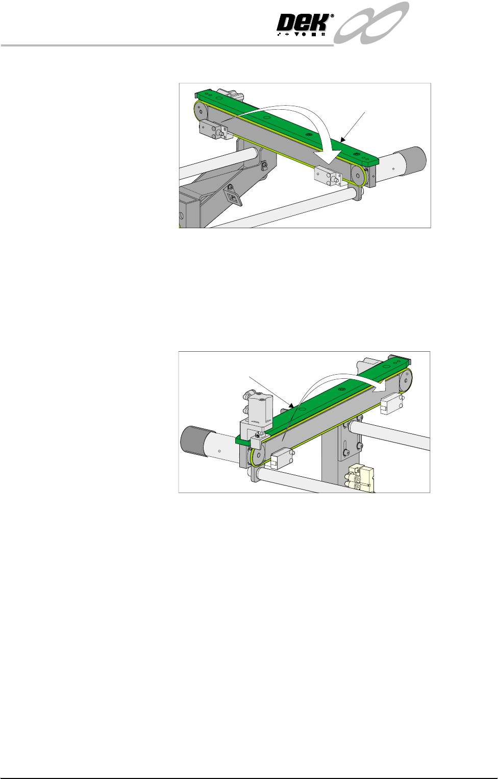
3. Gain access to the left hand auxiliary conveyor sensor.
4. Remove the two sensor securing screws and remove the sensor from the
mounting bracket.
5. Remove the two bolts securing the sensor mounting bracket to the front
INFINITY
EX
HIGH THROUGHPUT CONVEYOR MODULE
ADJUSTMENTS AND SETTINGS
16.48 Technical Reference Manual Chapter Issue 1 Aug 02
conveyor rail.
6. Refit the mounting bracket to left hand conveyor front rail using the outer-
most bracket mounting holes and refit the sensor removed in Step 4 to the
mounting bracket.
7. Identify the right hand auxiliary conveyor sensor, remove the two sensor
securing screws and remove the sensor.
8. Remove the two bolts securing the sensor mounting bracket to the front
conveyor rail.
9. Refit the mounting bracket to right hand conveyor front rail using the
innermost bracket mounting holes and refit the sensor removed in Step 7 to
the mounting bracket.
10.Identify the downline conveyor board stop fitted to the right hand auxiliary
conveyor.
11.Disconnect the two 4mm pneumatic pipes feeding the conveyor board stop.
12.Remove the pneumatic elbow connectors to gain access to the two 3mm allen
screws securing the board stop bracket to the conveyor rail.
Left Hand
Auxiliary Conveyor
Right Hand
Auxiliary Conveyor
INFINITY
EX
HIGH THROUGHPUT CONVEYOR MODULE
ADJUSTMENTS AND SETTINGS
Chapter Issue 1 Aug 02 Technical Reference Manual 16.49
13.Withdraw the allen screws and remove the board stop bracket from the rail.
14.To orientate the downline conveyor board stop for fitment to the left hand
auxiliary conveyor, remove the small pan head screw securing the board stop
bracket to the actuator rod.
15.Loosen the grubscrew on the board stop bracket and rotate the bracket 180°;
re-tighten the grubscrew.
NOTE
Ensure the grubscrew is located onto the flat side of the actuator rod.
16.Secure the board stop bracket to the actuator rod by refitting the pan head
screw.
17.Fit the downline board stop to the left hand auxiliary conveyor front rail
utilizing the existing securing points and the 3mm allen screws.
NOTE
Ensure the board stop bracket is orientated in the correct direction, ie angled
face of bracket towards the machine.
18.Disconnect the two pneumatic pipes supplying the conveyor board stop fitted
to the inboard end of the left hand auxiliary conveyor from solenoid (SOL
02).
19.Re-route the two pneumatic pipes to the downline conveyor board stop fitted
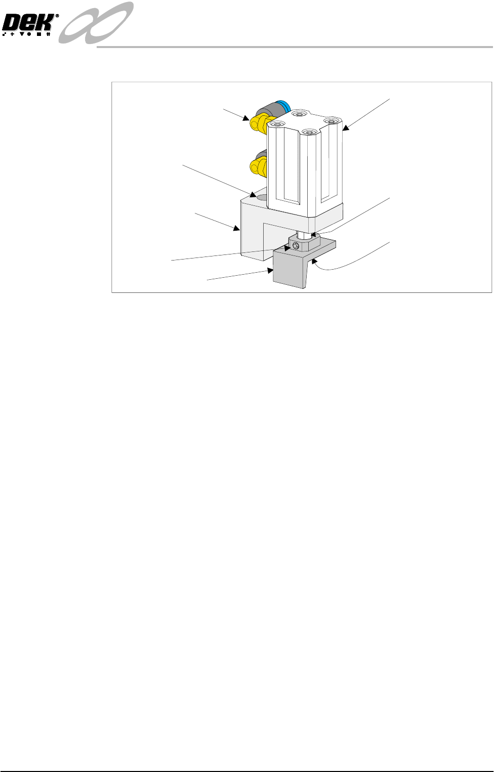
Pneumatic Elbow Joints
(2 Positions)
3mm Allen Screw
(2 Positions)
Securing Bracket
Board Stop Actuator
(Double Acting Cylinder)
Actuator Rod
Pan Head Securing
Screw (Underside of
Bracket)
Board Stop Bracket
Grubscrew