Infinity EX High Throughput Conveyor Module.pdf - 第50页
INFINITY EX HIGH THROUG HPUT CONVEY OR MODULE ADJUS TMEN TS AND SE TTINGS 16.5 0 Technical Reference Manual C hapter Issue 1 Aug 02 to the outboard e nd of the left hand auxiliary con ve yor . 20. Disconnect the two pneu…
INFINITY
EX
HIGH THROUGHPUT CONVEYOR MODULE
ADJUSTMENTS AND SETTINGS
Chapter Issue 1 Aug 02 Technical Reference Manual 16.49
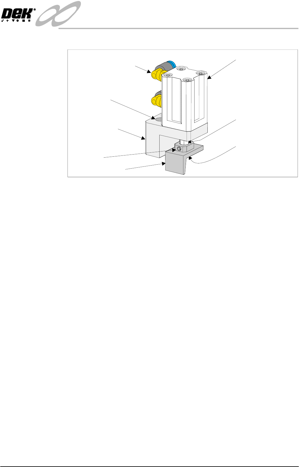
13.Withdraw the allen screws and remove the board stop bracket from the rail.
14.To orientate the downline conveyor board stop for fitment to the left hand
auxiliary conveyor, remove the small pan head screw securing the board stop
bracket to the actuator rod.
15.Loosen the grubscrew on the board stop bracket and rotate the bracket 180°;
re-tighten the grubscrew.
NOTE
Ensure the grubscrew is located onto the flat side of the actuator rod.
16.Secure the board stop bracket to the actuator rod by refitting the pan head
screw.
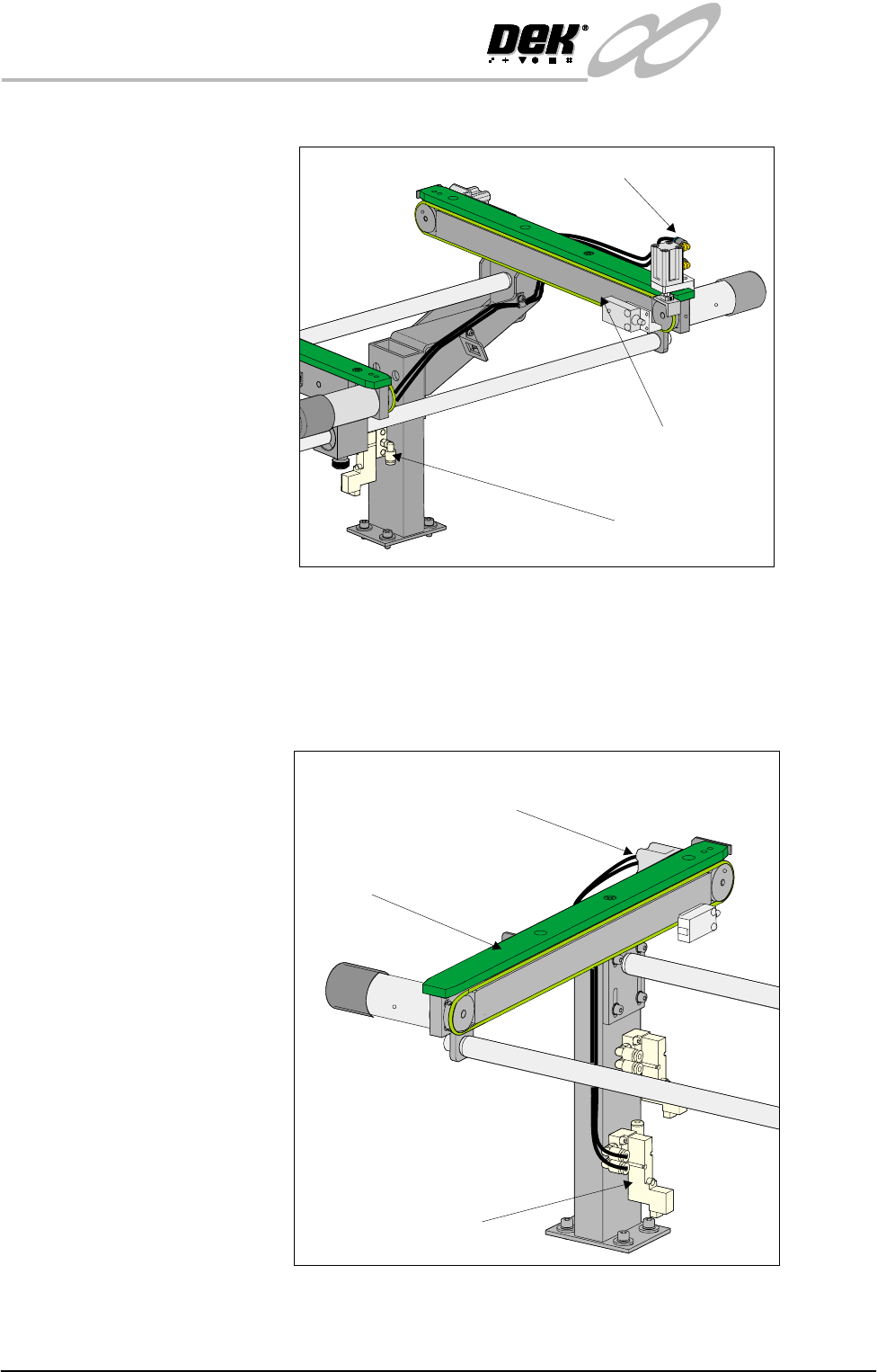
17.Fit the downline board stop to the left hand auxiliary conveyor front rail
utilizing the existing securing points and the 3mm allen screws.
NOTE
Ensure the board stop bracket is orientated in the correct direction, ie angled
face of bracket towards the machine.
18.Disconnect the two pneumatic pipes supplying the conveyor board stop fitted
to the inboard end of the left hand auxiliary conveyor from solenoid (SOL
02).
19.Re-route the two pneumatic pipes to the downline conveyor board stop fitted
Pneumatic Elbow Joints
(2 Positions)
3mm Allen Screw
(2 Positions)
Securing Bracket
Board Stop Actuator
(Double Acting Cylinder)
Actuator Rod
Pan Head Securing
Screw (Underside of
Bracket)
Board Stop Bracket
Grubscrew
INFINITY
EX
HIGH THROUGHPUT CONVEYOR MODULE
ADJUSTMENTS AND SETTINGS
16.50 Technical Reference Manual Chapter Issue 1 Aug 02
to the outboard end of the left hand auxiliary conveyor.
20.Disconnect the two pneumatic pipes from solenoid (SOL 01) supplying print
station conveyor board stop fitted to the inboard end of the right hand
conveyor.
21.Route the pneumatic pipes from solenoid (SOL 03) to the board stop, this
now configures the board stop from the print station board stop to the upline
board stop.
22.Remove the redundant pneumatic output pipes emerging from solenoid
(SOL 01).
Left Hand
Auxiliary Conveyor
Pneumatic Solenoid
(SOL 02)
Downline Conveyor
Board Stop
Pneumatic Solenoid
(SOL 03)
Right Hand
Auxiliary Conveyor
Print Station Board Stop
Now Configured as
Upline Board Stop
INFINITY
EX
HIGH THROUGHPUT CONVEYOR MODULE
ADJUSTMENTS AND SETTINGS
Chapter Issue 1 Aug 02 Technical Reference Manual 16.51
23.Fit two new 4mm pneumatic pipes to the solenoid (SOL 01) output ports A
& B and route the pipes to the left hand auxiliary conveyor.
24.Loom the new pneumatic pipes to the upline conveyor board stop fitted to
the inboard end of the left hand auxiliary conveyor. The board stop now is
configured as the print station board stop.
25.Gain access to the M27 HTC Controller enclosure.
26.Remove the four M27 enclosure securing screws.
27. Pull the M27 enclosure from its chassis mount and lower on the chassis hinge
to access the rear panel socket array.
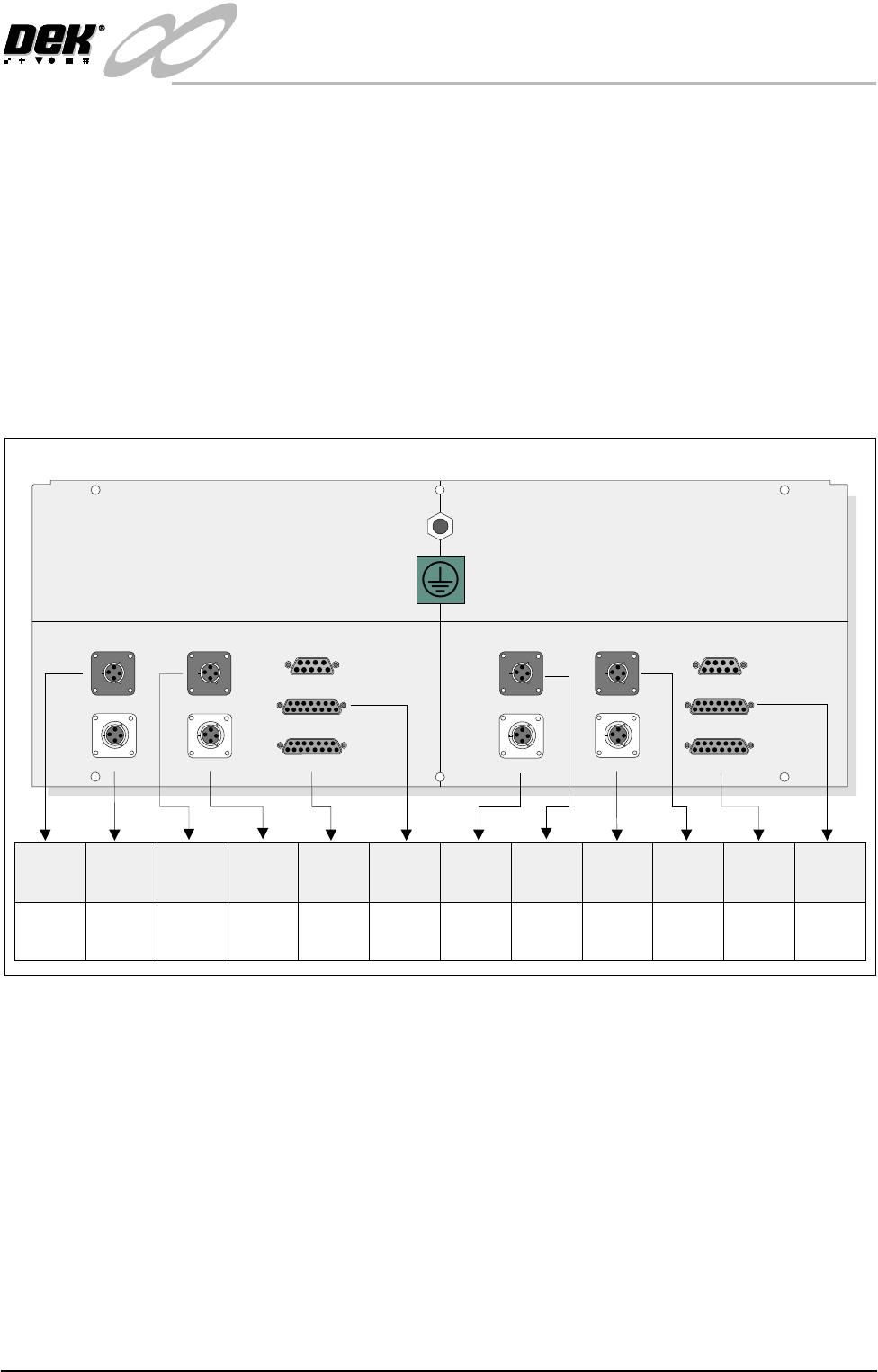
28. To configure the M27 enclosure for right to left throughput direction, connect
the enclosure as shown in the graphic below:
29.On completion, refit the M27 enclosure.
30.Refit the external pneumatic connection to the external services panel.
31.Power up and initialize the machine. If required, remove the head prop and
lower the head.
32.In Set Prefs menu, ensure the Transport Mode option is selected to Right to
Left.
Left to Right
Configuration
To change the configuration of the machine from Right to Left to Left to Right
throughput carry out the following:
1. If required, raise the head and insert the head prop
2. Power the machine and disconnect the quick release pneumatic connection
at the machine’s external services panel.
3. Gain access to the left hand auxiliary conveyor sensor.
M27SK04 M27SK12M27SK18 M27SK19
M27SK08 (L/H)M27SK20 (L/H) M27SK08 (R/H)M27SK21 (R/H)
LANE A (LEFT) LANE A (RIGHT)
M27SK01 (L/H) M27SK01 (R/H)
M27SK02 (L/H) M27SK02 (R/H)
M27SK03 M27SK11
Inverted View on Rear of 3-Stage Conveyor Controller M27
M27SK20
(L/H)
M27PL20
(SOL 02)
N/C
N/C
N/C
M27PL08
(SOL 01)
M27PL21
(SOL 03)
M27PL04/
M27PL18
M27PL12/
M27PL19
M27PL01
(Loom
160622)
M27PL02
(Loom
160622)
M27PL02
(Loom
160645 or
160631)
M27PL01
(Loom
160643 or
160631)
M27SK04
M27SK08
(L/H)
M27SK18
M27SK01
(L/H)
M27SK02
(L/H)
M27SK12
M27SK21
(R/H)
M27SK19
M27SK08
(R/H)
M27SK01
(R/H)
M27SK02
(R/H)