Infinity EX High Throughput Conveyor Module.pdf - 第7页
INFINITY EX HIGH THROUG HPUT CONVE YOR MODULE MECHANICAL DETAIL Chapter Issu e 1 Aug 02 Technical Reference Manual 16.7 Fixed Rail Print Station The f ixed rai l print station houses four pneumatic cylinders, used to ope…
INFINITY
EX
HIGH THROUGHPUT CONVEYOR MODULE
MECHANICAL DETAIL
16.6 Technical Reference Manual Chapter Issue 1 Aug 02
whilst a board is still on the downline auxiliary conveyor. (Or when a transfer
between the downline conveyor and the downline machine is taking place.)
Each board stop is activated by the ‘Downline available’ FMI signal from the
section/machine downline of it, thus preventing a board from leaving the con-
veyor until the section/machine asks for it.
CAUTION
CONVEYOR BOARD STOP. Conveyor board stops may be damaged by the
printing of heavy boards, thus preventing the overshoot of these boards. To
minimise this effect, adjust the position of the relevant board stop sensor if
damage to the conveyor board stops occur (refer to Adjustments and
Settings section of this chapter).
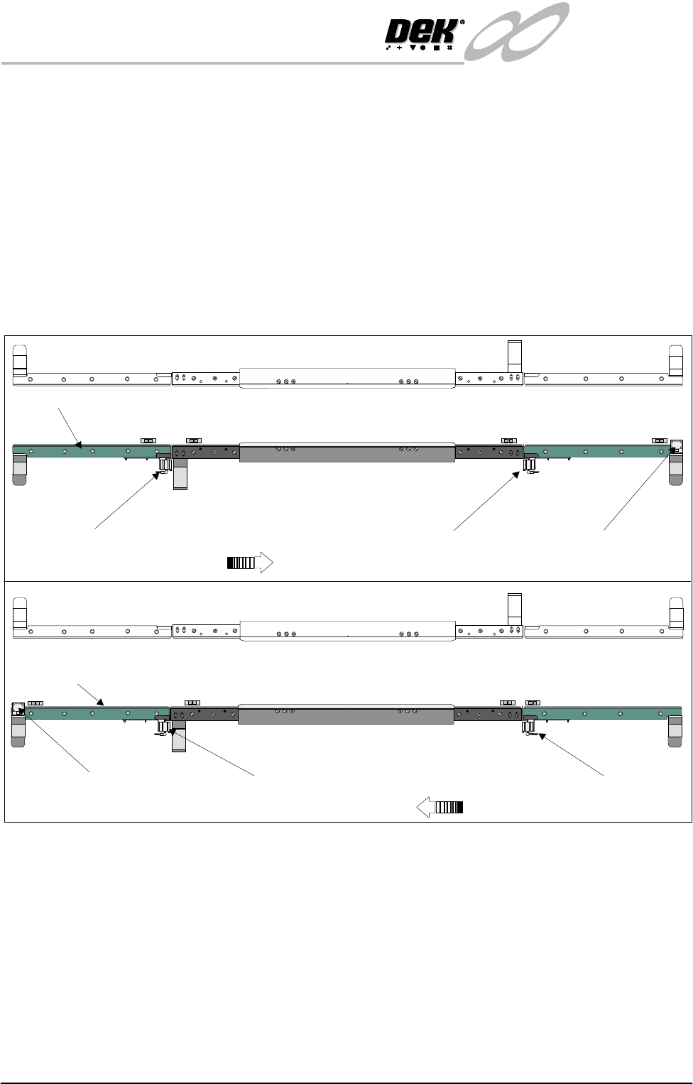
Figure 16-3 Board Stop Positions
Moving Rail Print
Station
The moving rail print station is transported into position, as set by the board
width parameter in the current product file, by two drive shafts. A single stepper
motor drives the right hand drive shaft via a drive belt. Transmission between
the two drive shafts is achieved via pulleys and a drive belt.
The moving print station houses four pneumatic cylinders, two of which, are
used to operate the board clamps to secure the board against the transport belt
and the belt support web, during the print cycle. Board clamps or the optional
foil-less clamps or snugger assemblies are secured to the top of the print station.
A transport belt motor is attached to the right hand side of the rear face of the
print station, driving one of the two transport belt pulleys on the front face of the
print station.
WARNING SHARP EDGE
WARNING SHARP EDGE
PATENT No 5157438
PATENT No 5157438
WARNING SHARP EDGE
WARNING SHARP EDGE
PATENT No 5157438
PATENT No 5157438
Left to Right Board Movement
Right to Left Board Movement
K
E
Y
E
N
C
E
P
Z
-
4
2
L
K
E
Y
E
N
C
E
P
Z
-
4
2
L
K
E
Y
E
N
C
E
P
Z
-
4
2
L
K
E
Y
E
N
C
E
P
Z
-
4
2
L
WARNING SHARP EDGE
PATENT No 5157438
K
E
Y
E
N
C
E
P
Z
-
4
2
L
K
E
Y
E
N
C
E
P
Z
-
4
2
L
K
E
Y
E
N
C
E
P
Z
-
4
2
L
K
E
Y
E
N
C
E
P
Z
-
4
2
L
WARNING SHARP EDGE
PATENT No 5157438
Fixed Rail
Fixed Rail
Upline Board Stop
Upline Board Stop
Downline Board Stop
Downline Board Stop
Print Station Board Stop
Print Station Board Stop
INFINITY
EX
HIGH THROUGHPUT CONVEYOR MODULE
MECHANICAL DETAIL
Chapter Issue 1 Aug 02 Technical Reference Manual 16.7
Fixed Rail Print
Station
The fixed rail print station houses four pneumatic cylinders, used to operate the
board clamps to secure the board against the transport belt and the belt support
web, during the print cycle. Board clamps or the optional foil-less clamps or
snugger assemblies are secured to the top of the print station.
A transport belt motor is attached to the left hand side of the rear face of the print
station, driving one of the two transport belt pulleys on the front face of the print
station.
On the front face of the print station, two background suppressed opto’s are fitted
below the belt support web, designated Board at Left and Board at Right sensors.
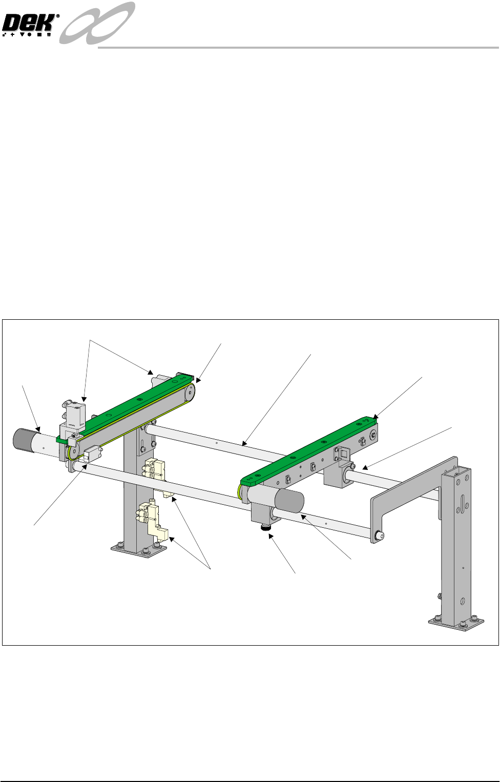
Auxiliary Conveyors
Right Hand
Conveyor
The right hand auxiliary conveyor can be configured from the machine’s down-
line conveyor to the upline conveyor, by the removal of the conveyor board stop
at the end of the conveyor rail. Also, the auxiliary conveyor sensor is moved
from it’s outboard position as the downline auxiliary sensor inboard as the upline
auxiliary sensor.
Figure 16-4 Right Hand Auxiliary Conveyor
Each of the conveyor’s rails house a transport belt motor driving one of two belt
pulleys on the front face of the rail.
Two pneumatic solenoid valves, type 5/2 are fitted to the fixed rail support to
control the distribution of compressed air to the conveyor board stops.
Rail width adjustment is achieved by manually adjusting the position of the
moving rail along the conveyor guide shafts on the two bearing blocks. The rail
Rear View of Right Hand Auxiliary Conveyor
(Configured as Downline Conveyor)
Transport Belt
Motor
Transport Belt
Motor
Conveyor Board Stop
Auxiliary Conveyor
Sensor
Pneumatic Solenoid Locking
Thumbscrew
Bearing Block
(in 2 positions)
Fixed Rail
Moving Rail
Guide Shaft
(in 2 positions)
INFINITY
EX
HIGH THROUGHPUT CONVEYOR MODULE
MECHANICAL DETAIL
16.8 Technical Reference Manual Chapter Issue 1 Aug 02
is secured in position by the locking thumbscrew on right hand bearing block.
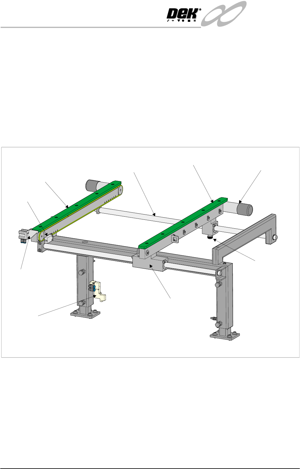
Left Hand Conveyor The left hand auxiliary conveyor can be configured from the machine’s upline
conveyor to the downline conveyor, by the addition of the conveyor board stop
at the end of the conveyor rail. Also, the auxiliary conveyor sensor is moved
from it’s inboard position as the upline auxiliary sensor outboard as the downline
auxiliary sensor.
Each of the conveyor’s rails house a transport belt motor driving one of two belt
pulleys on the front face of the rail.
A single pneumatic solenoid valve, type 5/2 is fitted to the fixed rail support to
control the distribution of compressed air to the conveyor board stop.
Figure 16-5 Left Hand Auxiliary Conveyor
Rail width adjustment is achieved by manually adjusting the position of the
moving rail along the conveyor guide shafts on the two bearing blocks. The rail
is secured in position by the locking thumbscrew on left hand bearing block.
The left hand conveyor rails are seven inches longer than the right hand con-
veyor, this allows for manual loading during machine qualification.
Rear View of Left Hand Auxiliary Conveyor
(Configured as Upline Conveyor)
Transport Belt Motor
(in 2 positions)
Conveyor Board
Stop
Auxiliary Conveyor
Sensor
Pneumatic Solenoid
Locking
Thumbscrew
Bearing Block
(in 2 positions)
Fixed Rail
Moving Rail
Guide Shaft
(in 2 positions)