TR7600 SIII_Electrical_Diagrams_en_v_2_0_3 - 第27页
TR7600 SII I User Guide – Electrical Di agrams Figure 20: Load er and Unloader Cab l e PIN1~PIN6 1 2 3 4 5 6 7 8 9 10 11 12 13 14 PIN1~PIN6 1 2 3 4 5 6 7 8 9 10 11 12 13 14 1 2 3 4 5 6 7 8 9 10 11 12 13 14 1 2 3 4 5 6 7 …
Test Research, Inc.
18
TR7600 SIII User Guide – Electrical Diagrams
1.15.1 Linking with Loader
SMEMA Connections:
PORT1 – UP LINE
Y24
Black (1) / Green (2) Ready
X2A
Red (3) / Blue (4) Board Available
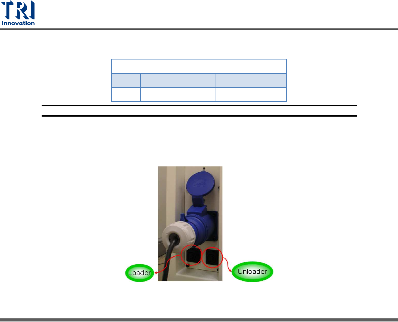
Figure 18: Loader Socket Position
Located below the power supply socket in the back of the equipment is I/O PORT1. Connect the connector, and there are three sets
of different colored wire pairs at the connector end. These are: Black-Green (Y24) for requesting board from Loader and Red-Blue
(X2A) reserved INPUT connector. Connect the Black-Green connector to the Loader Board Request connection. (We use the
standard SMEMA signal. If this is different due to differences in manufacturer, contact the front stage manufacturer to acquire the
connection data.)
Figure 19: Loader and Unloader Socket Position
TR7600 SIII User Guide – Electrical Diagrams
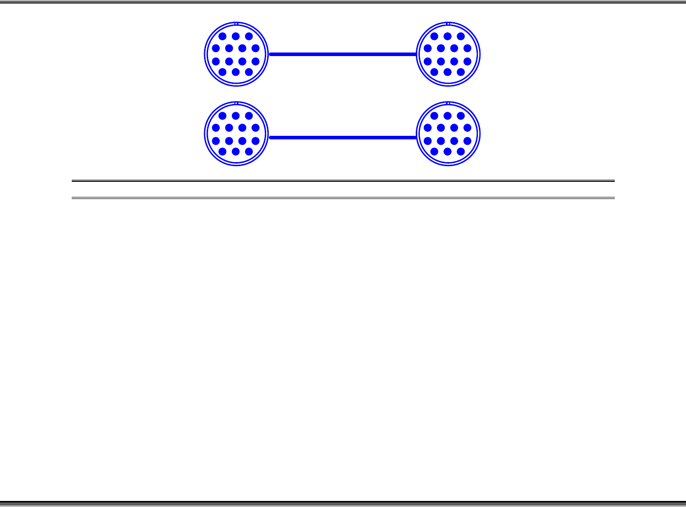
Figure 20: Loader and Unloader Cable
PIN1~PIN6
1 2 3
4 5 6 7
8 9 10 11
12 13 14
PIN1~PIN6
1 2 3
4 5 6 7
8 9 10 11
12 13 14
1 2 3
4 5 6 7
8 9 10 11
12 13 14
1 2 3
4 5 6 7
8 9 10 11
12 13 14
Test Research, Inc.
20
TR7600 SIII User Guide – Electrical Diagrams
1.15.2 Linking with Unloader
SMEMA Connections
PORT2 – DOWN LINE
X4B
Black (1) / Green (2) Ready
Y26
Red (3) / Blue (4) Board Available
Y25
Yellow (5) / White (6) PASS: Short; NG: Open
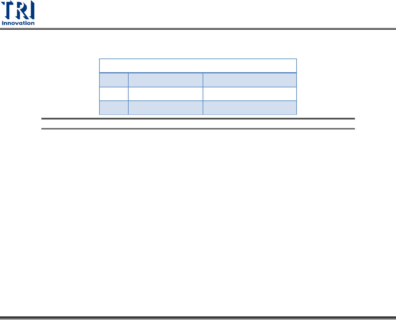
Figure 21: Unloader Socket
Located below the power supply socket in the back of the equipment is I/O PORT2. Connect the connector, and there are three sets
of different colored wire pairs at the connector end. These are: Black-Green (X4B) for receiving READY board request signal from
the Unloader, Red-Blue (Y26) for sending board unload signal to the Unloader and the Yellow-White (Y25) TEST PASS signal
connector. Connect the Black-Green connector with the Unloader’s connector for sending READY board request signal. Then
connect the Yellow-White connector with the Unloader's connector for receiving TEST PASS signal. (We use the standard SMEMA
signal. If this is different due to differences in manufacturer, contact the rear stage manufacturer to acquire the connection data.)