1OPERATION_.pdf - 第113页
Magnified View of Inset A Fig . 2.18 Note : & = 37.9 - ( P . C . B . Thickness ) L = £ + 5.5 Unit : mm 2 — 23 糊 mm ACP 01 EOP 2 - 23 2.6 Program Change • When P . C . B . thickness is changed , P . C . B . support pi…
2.6
Program
Change
(
3
)
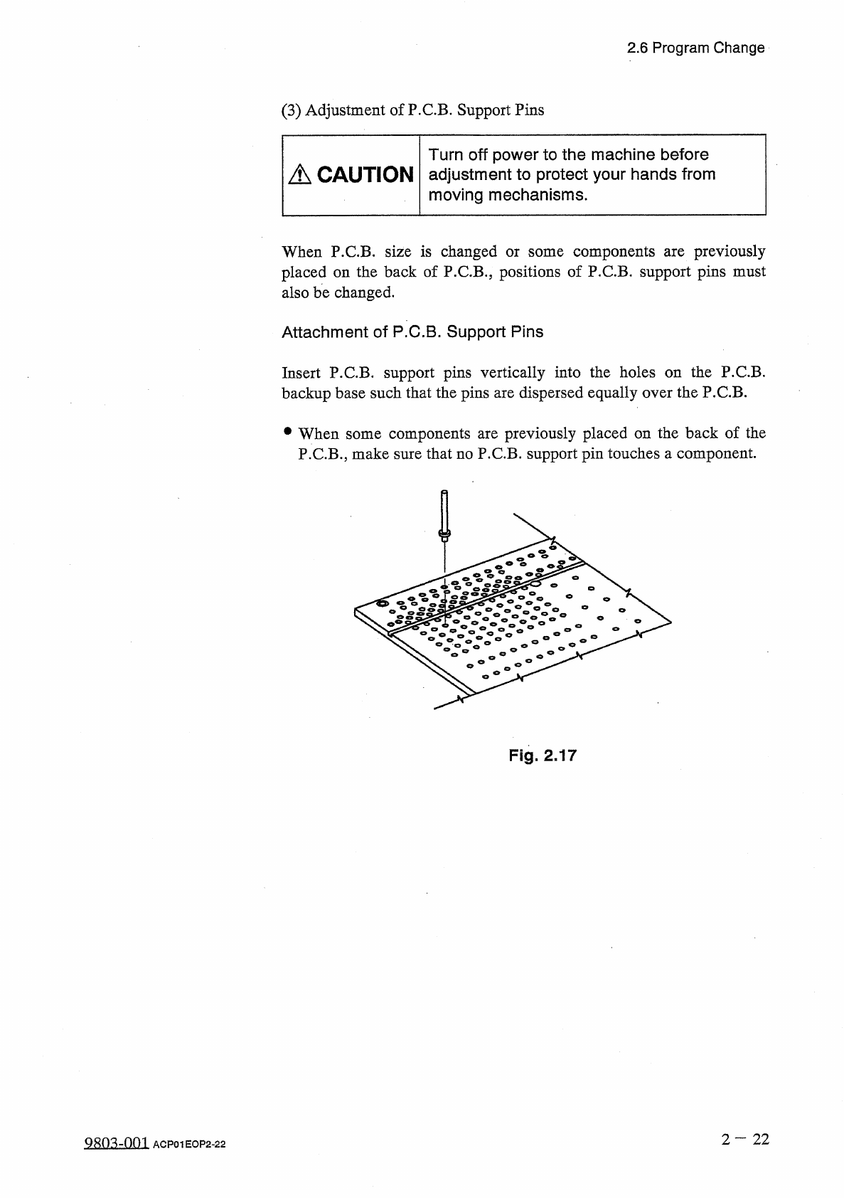
Adjustment
of
P
.
C
.
B
.
Support
Pins
Turn
off
power
to
the
machine
before
adjustment
to
protect
your
hands
from
moving
mechanisms
.
A
CAUTION
When
P
.
C
.
B
.
size
is
changed
or
some
components
placed
on
the
back
of
P
.
C
.
B
.
,
positions
of
P
.
C
.
B
.
support
pins
must
also
be
changed
.
previously
are
Attachment
of
P
.
C
.
B
.
Support
Pins
Insert
P
.
CB
.
support
pins
vertically
into
the
holes
on
the
P
.
C
.
B
.
backup
base
such
that
the
pins
are
dispersed
equally
over
the
P
.
C
.
B
.
components
are
previously
placed
on
the
back
of
the
P
.
C
.
B
.
,
make
sure
that
no
P
.
C
.
B
.
support
pin
touches
a
component
.
參
When
some
Fig
.
2.17
2
—
22
QR
03
-
001
ACP
01
EOP
2
-
22
Magnified
View
of
Inset
A
Fig
.
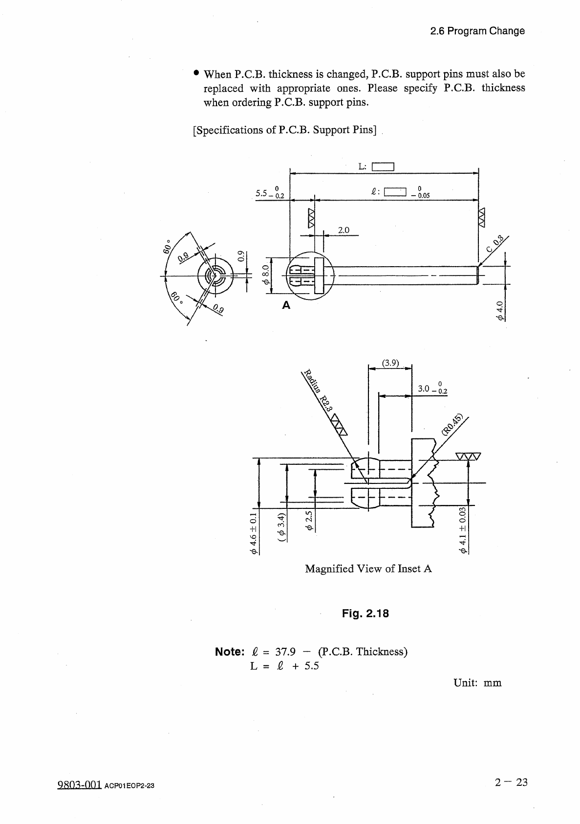
2.18
Note
:
&
=
37.9
-
(
P
.
C
.
B
.
Thickness
)
L
=
£
+
5.5
Unit
:
mm
2
—
23
糊
mm
ACP
01
EOP
2
-
23
2.6
Program
Change
•
When
P
.
C
.
B
.
thickness
is
changed
,
P
.
C
.
B
.
support
pins
must
also
be
Please
specify
P
.
C
.
B
.
thickness
replaced
with
appropriate
when
ordering
P
.
C
.
B
.
support
pins
.
ones
.
[
Specifications
of
P
.
C
.
B
.
Support
Pins
]
L
:
I I
o
o
[
ZZJ
5.5
-
0.05
0.2
2.0
4
I
O
$
(
3.9
)
o
-
0.2
V
-
leodl
+
llr
寸 令
「
I
3
E
S
.
Z
-
&
-
(
re
-
Q
-
l
)
ro
+
l
9
>
-
©
.
2.6
Program
Change
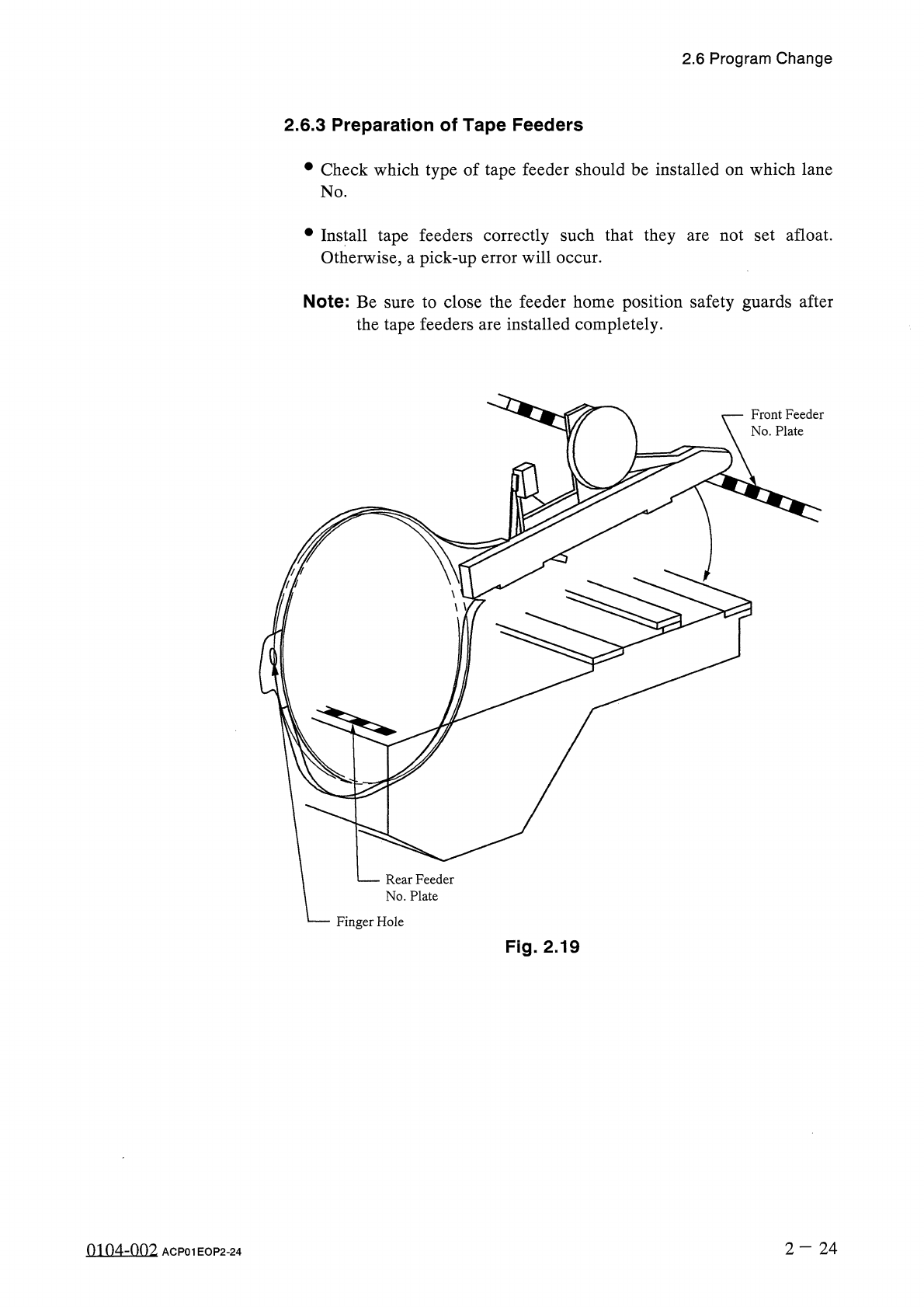
2.6
.
3
Preparation
of
Tape
Feeders
•
Check
which
type
of
tape
feeder
should
be
installed
on
which
lane
No
.
•
Install
tape
feeders
correctly
such
that
they
Otherwise
,
a
pick
-
up
error
will
occur
.
not
set
afloat
.
are
Note
:
Be
sure
to
close
the
feeder
home
position
safety
guards
after
the
tape
feeders
are
installed
completely
.
Front
Feeder
No
.
Plate
Rear
Feeder
No
.
Plate
Finger
Hole
Fig
.
2.19
2
—
2 4
0104
-
002
ACP
01
EOP
2
-
24