1OPERATION_.pdf - 第116页
2.6 Program Change 2.6 . 5 All Data Clear Operation for Feeder ( B ) Offset The feeder ( B ) offset data is used to correct the positional deviation in component pick - up positions caused due to the variation in tape fe…
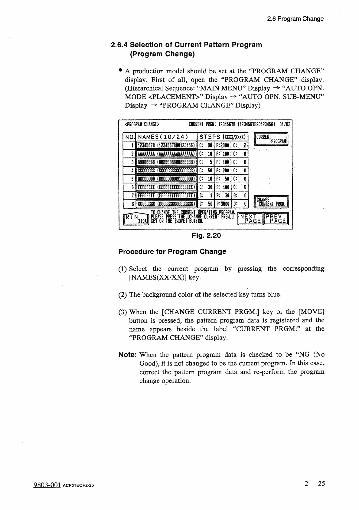
2.6
Program
Change
2.6
.
4
Selection
of
Current
Pattern
Program
(
Program
Change
)
•
A
production
model
should
be
set
at
the
“
PROGRAM
CHANGE
”
display
.
First
of
all
,
open
the
“
PROGRAM
CHANGE
”
display
.
(
Hierarchical
Sequence
:
“
MAIN
MENU
”
Display
—
“
AUTO
OPN
.
AUTO
OPN
.
SUB
-
MENU
”
Display
)
MODE
<
PLACEMENT
>
”
Display
Display
PROGRAM
CHANGE
:
<
PB
0
GRAM
CHANGE
〉
CURRENT
PRGU
:
12345678
(
1234567890123456
)
01
/
03
STEPS
(
XXXX
/
XXXX
)
NAMES
(
10
/
24
)
NO
0
:
.
'
2
〕
P
:
C
:
80
12345678
(
12345678901234
SS
)
6
P
:
WO
AAAAAAAA
(
AAAAAAAAAAAAAAAA
)
C
:
10
2
0
:
p
:
m
BB
8
BBBBB
(
B
觀刪
8
的
BBB
唧
1
3
C
:
5
0
:
0
P
:
200
CCCCCCCC
(
CCCCCCCCCCCCCCCC
)
C
:
50
0
:
0
4
DDDDDDDO
(
DDDDDDDDDDDDDDDD
)
C
:
10
P
:
SO
0
:
t
)
5
P
:
100
EEEEEEEE
(
E
£
E
|
EE
|
E
|
£
E
£
E
|
E
£
|
0
:
0
C
:
30
6
P
:
.
30
FFFFFFFF
(
fFFFFFFFFFfFFfFF
)
C
:
1
Q
:
0
7
CCII
[
HT
?
mj
p
:
o
:
it
GG
666666
(
88
G
6
S
6
GG
66
SGG
66
G
)
8
C
:
50
翩廳
N
E
PRP
Fig
.
2.20
Procedure
for
Program
Change
(
1
)
Select
the
current
program
by
pressing
the
corresponding
[
NAMES
(
XX
/
XX
)
]
key
.
(
2
)
The
background
color
of
the
selected
key
turns
blue
.
(
3
)
When
the
[
CHANGE
CURRENT
PRGM
.
]
key
or
the
[
MOVE
]
button
is
pressed
,
the
pattern
program
data
is
registered
and
the
name
appears
beside
the
label
“
CURRENT
PRGM
:
”
at
the
“
PROGRAM
CHANGE
”
display
.
Note
:
When
the
pattern
program
data
is
checked
to
be
“
NG
(
No
Good
)
,
it
is
not
changed
to
be
the
current
program
.
In
this
case
,
correct
the
pattern
program
data
and
re
-
perform
the
program
change
operation
.
2
—
2 5
QRm
-
001
ACP
01
EOP
2
-
25
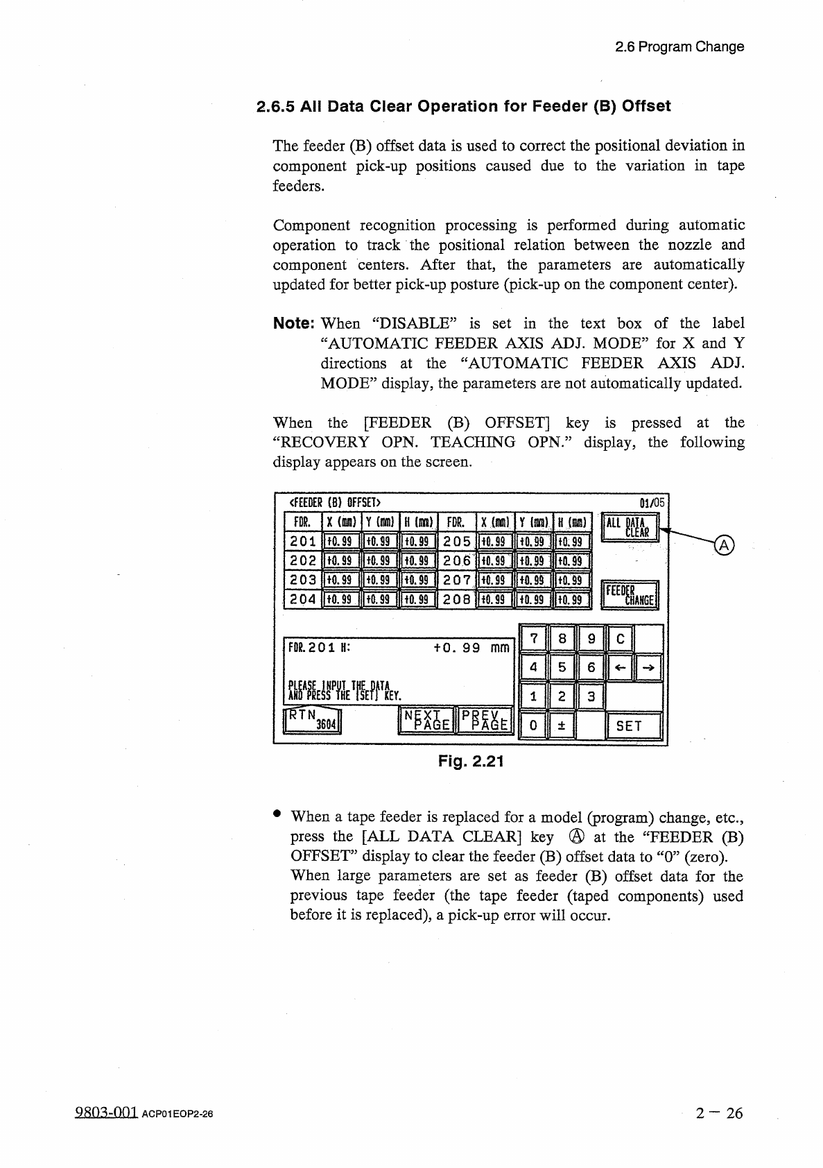
2.6
Program
Change
2.6
.
5
All
Data
Clear
Operation
for
Feeder
(
B
)
Offset
The
feeder
(
B
)
offset
data
is
used
to
correct
the
positional
deviation
in
component
pick
-
up
positions
caused
due
to
the
variation
in
tape
feeders
.
Component
recognition
processing
is
performed
during
automatic
operation
to
track
the
positional
relation
between
the
nozzle
and
component
centers
.
After
that
,
the
parameters
updated
for
better
pick
-
up
posture
(
pick
-
up
on
the
component
center
)
.
automatically
are
Note
:
When
“
DISABLE
”
is
set
in
the
text
box
of
the
label
“
AUTOMATIC
FEEDER
AXIS
ADJ
.
MODE
”
for
X
and
Y
directions
at
the
“
AUTOMATIC
FEEDER
AXIS
ADJ
.
MODE
”
display
,
the
parameters
are
not
automatically
updated
.
When
the
[
FEEDER
(
B
)
OFFSET
]
key
is
pressed
at
the
“
RECOVERY
OPN
.
TEACHING
OPN
.
”
display
,
the
following
display
appears
on
the
screen
.
<
f
£
EDER
⑻
OFFSET
)
01
/
05
X
(
咖
)
FDR
.
Y
m
)
H
(
!
IK
8
)
x
(
m
)
Y
(
Jim
)
FDR
.
H
(
咖
J
kLim
2
Q
5
H
0.89
HiOnfUf
ITOF
ItOF
201
tO
.
99
2
Q
6
ftorlnfUBi
|
tfl
.
39
IUfl
.
99
I
202
U
0.99
207
ltO
.
99
IK
0.9
M
[
fQ
9
40.99
203
SM
[
fOniTori
ww
\
208
Honr
?
onuon
204
7
8
9
c
FDR
.
201
H
:
fO
.
99
mm
5
4
6
ME
屬
ffTk
2
1
3
0
SET
±
Fig
.
2.21
•
When
a
tape
feeder
is
replaced
for
a
model
(
program
)
change
,
etc
.
,
press
the
[
ALL
DATA
CLEAR
]
key
@
at
the
“
FEEDER
(
B
)
OFFSET
”
display
to
clear
the
feeder
(
B
)
offset
data
to
“
0
”
(
zero
)
.
When
large
parameters
are
set
as
feeder
(
B
)
offset
data
for
the
previous
tape
feeder
(
the
tape
feeder
(
taped
components
)
used
before
it
is
replaced
)
,
a
pick
-
up
error
will
occur
.
980
^
-
001
2
—
26
ACP
01
EOP
2
-
26
2.7
Verification
of
Current
Pattern
Program
Data
2.7
Verification
of
Current
Pattern
Program
Data
2.7
.
1
P
.
E
.
C
.
Recognition
Test
The
P
.
E
.
C
.
camera
checks
the
coordinates
of
fiducial
marks
(
2
or
3
places
)
on
the
P
.
C
.
B
.
and
determines
the
deviation
from
theoretical
coordinates
.
Furthermore
,
this
function
is
used
to
automatically
correct
the
positional
deviations
of
the
placed
components
.
Refer
to
“
3.1
P
.
E
.
C
Recognition
Function
”
in
“
Chapter
3
Various
Functions
”
for
details
.
When
“
ON
”
is
set
in
the
“
P
.
E
.
C
.
RECOGNITION
”
text
box
at
the
“
OPERATION
DATA
”
display
,
follow
the
procedure
below
to
prepare
for
automatic
operation
.
Procedure
(
1
)
Turn
on
the
“
P
.
E
.
C
RECOG
LIGHT
”
switch
on
the
front
console
panel
and
then
turn
off
the
“
LIGHT
”
switch
.
(
2
)
Prepare
a
P
.
C
.
B
.
to
be
used
for
actual
production
and
make
a
P
.
E
.
C
.
recognition
test
to
verify
each
set
parameters
.
Refer
to
“
3.4
.
2
P
.
E
.
C
RECOGNITION
TEST
”
in
the
instruction
MAINTENANCE
P
.
E
.
C
.
recognition
test
.
①
Whenever
the
parameters
set
in
the
“
MARK
TYPE
”
,
“
MARK
SIZE
”
,
“
WINDOW
SIZE
”
,
“
RECOGNITION
ALGORITHM
'
“
FIDUCIAL
MARK
LEVEL
”
text
boxes
are
changed
,
be
sure
to
modify
the
original
pattern
program
data
.
Refer
to
“
2.11
Editing
of
P
.
E
.
C
Mark
Data
”
in
the
instruction
manual
“
SECTION
PROGRAMMING
MANUAL
”
for
details
how
to
modify
the
pattern
program
data
.
②
Determine
the
gain
and
level
data
of
Camera
#
3
(
for
P
.
E
.
C
Recognition
)
.
The
determined
gain
and
level
must
be
entered
in
the
offset
data
.
Refer
to
“
4.3
.
10
Camera
Offset
”
in
the
instruction
PROGRAMMING
MANUAL
)
for
details
on
the
offset
data
.
manual
(
SECTION
MANUAL
)
for
details
on
the
n
on
n
(
SECTION
manual
2
—
27
QR
0
^
-
0
fl
1
ACP
01
EOP
2
-
27