1OPERATION_.pdf - 第128页
2.11 Reset and Start Procedure from Emergency Stop ( Automatic Operation ( “ PLACE ” Mode ) ) 2.11 Reset and Start Procedure from Emergency Stop ( Automatic Operation ( “ PLACE ” Mode ) ) 2.11 . 1 Cause and Symptom of Em…
2.10
Interruption
of
Automatic
Operation
(
“
PLACE
”
Mode
)
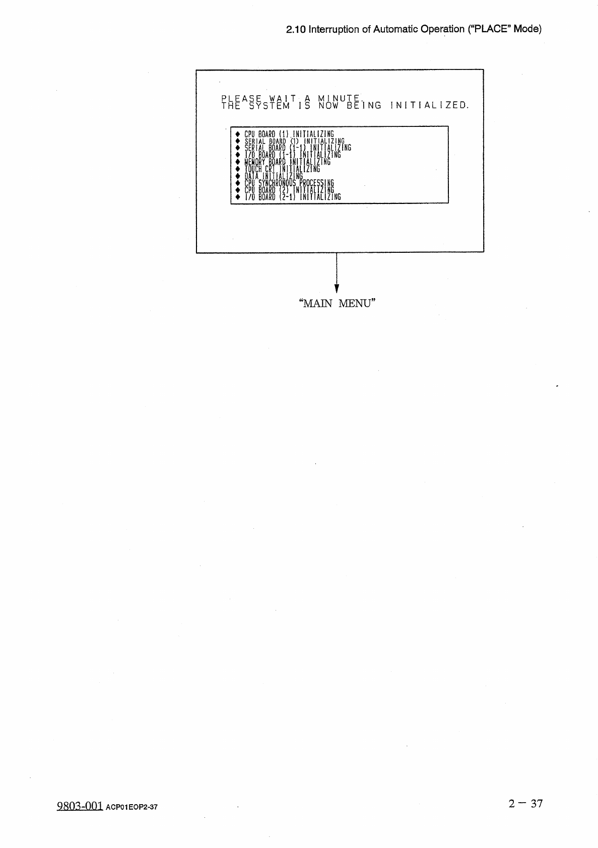
THEASYSTEMT
I
S
N
0
WUBE
*
l
NG
I N I T I A L I Z E D
.
CPU
BOARD
(
D
.
INiliALIZIHG
SERIAL
BOARD
(
1
)
INITIALIZING
—
(
1
-
1
)
INITIALIZING
1
INIIIALIZiNG
D
INITIALIZING
SERIAL
BOARD
I
/
O
BOARD
(
1
-
MEMORY
Mt
TOUCH
CRT
INITIALIZING
DATA
INITIALIZING
CPU
SYNCHRONOUS
PROCES
CPU
BOARD
(
2
)
INITIALi
I
/
O
BOARD
2
-
1
)
INITIAL
ZING
ni
“
MAIN
MENU
”
2
—
37
98034
)
03
ACP
01
EOP
2
-
37
2.11
Reset
and
Start
Procedure
from
Emergency
Stop
(
Automatic
Operation
(
“
PLACE
”
Mode
)
)
2.11
Reset
and
Start
Procedure
from
Emergency
Stop
(
Automatic
Operation
(
“
PLACE
”
Mode
)
)
2.11
.
1
Cause
and
Symptom
of
Emergency
Stop
(
1
)
Cause
•
The
machine
stops
when
the
[
EMERGENCY
STOP
]
button
is
pressed
.
•
The
machine
stops
when
power
failure
occurs
or
the
air
pressure
drops
.
(
2
)
Symptom
•
When
the
[
EMERGENCY
STOP
]
button
is
pressed
or
the
supplied
air
pressure
drops
,
the
LED
of
the
[
POWER
ON
]
button
illuminates
in
red
,
indicating
that
power
to
the
loads
is
shut
off
.
•
When
power
failure
occurs
,
the
power
to
the
machine
is
completely
shut
off
.
2.11
.
2
Reset
and
Start
Procedure
from
Emergency
Stop
(
Automatic
Operation
(
“
PLACE
”
Mode
)
)
(
1
)
Before
pressing
the
[
POWER
ON
]
button
,
check
the
cause
of
emergency
stop
and
the
condition
of
each
individual
device
.
Then
,
eliminate
the
cause
.
•
Checking
the
Condition
of
Each
Individual
Device
•
Taking
Remedial
Measures
against
Picked
Components
•
Setting
a
P
.
C
.
B
.
in
the
middle
of
transfer
to
its
correct
position
•
Checking
the
Air
Pressure
(
2
)
Check
for
fallen
components
and
remove
them
if
any
.
Check
the
area
below
the
vacuum
nozzles
located
between
station
Nos
.
1
through
11
.
When
a
component
has
fallen
on
the
camera
at
station
No
.
5
(
recognition
station
)
,
be
sure
to
remove
it
.
Otherwise
,
a
recognition
error
will
occur
after
the
machine
is
powered
up
again
.
A
CAUTION
2
—
38
糊
mm
ACP
01
EOP
2
-
38
2.11
Reset
and
Start
Procedure
from
Emergency
Stop
(
Automatic
Operation
(
“
PLACE
”
Mode
)
)
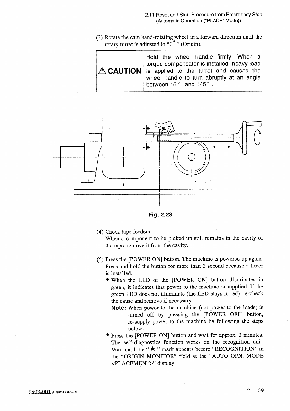
(
3
)
Rotate
the
cam
hand
-
rotating
wheel
in
a
forward
direction
until
the
rotary
turret
is
adjusted
to
“
0
”
(
Origin
)
.
Hold
the
wheel
handle
firmly
.
When
a
torque
compensator
is
installed
,
heavy
load
is
applied
to
the
turret
and
causes
the
wheel
handle
to
turn
abruptly
at
an
angle
between
15
°
and
145
°
■
A
CAUTION
c
Fig
.
2.23
(
4
)
Check
tape
feeders
.
When
a
component
to
be
picked
up
still
remains
in
the
cavity
of
the
tape
,
remove
it
from
the
cavity
.
(
5
)
Press
the
[
POWER
ON
]
button
.
The
machine
is
powered
up
again
.
Press
and
hold
the
button
for
more
than
1
second
because
a
timer
is
installed
.
•
When
the
LED
of
the
[
POWER
ON
]
button
illuminates
in
green
,
it
indicates
that
power
to
the
machine
is
supplied
.
If
the
green
LED
does
not
illuminate
(
the
LED
stays
in
red
)
,
re
-
check
the
cause
and
remove
if
necessary
.
Note
:
When
power
to
the
machine
(
not
power
to
the
loads
)
is
turned
off
by
pressing
the
[
POWER
OFF
]
button
,
re
-
supply
power
to
the
machine
by
following
the
steps
below
.
參
Press
the
[
POWER
ON
]
button
and
wait
for
approx
.
3
minutes
.
the
recognition
unit
,
mark
appears
before
“
RECOGNITION
”
in
The
self
-
diagnostics
function
works
on
Wait
until
the
the
“
ORIGIN
MONITOR
”
field
at
the
“
AUTO
OPN
.
MODE
〈
PLACEMENT
〉
,
,
display
.
2
-
39
QRQ
^
-
001
ACP
01
EOP
2
-
39