1OPERATION_.pdf - 第142页
3.4 Priority Sorting Function Placement Data P 1 Placement Data P 2 Placement Data P 3 Placement Data P 4 Placement Order Placement Order Placement Order Placement Order Step No . C Step No . C Step No . Step No . C C P …
3.4
Priority
Sorting
Function
3.4
Priority
Sorting
Function
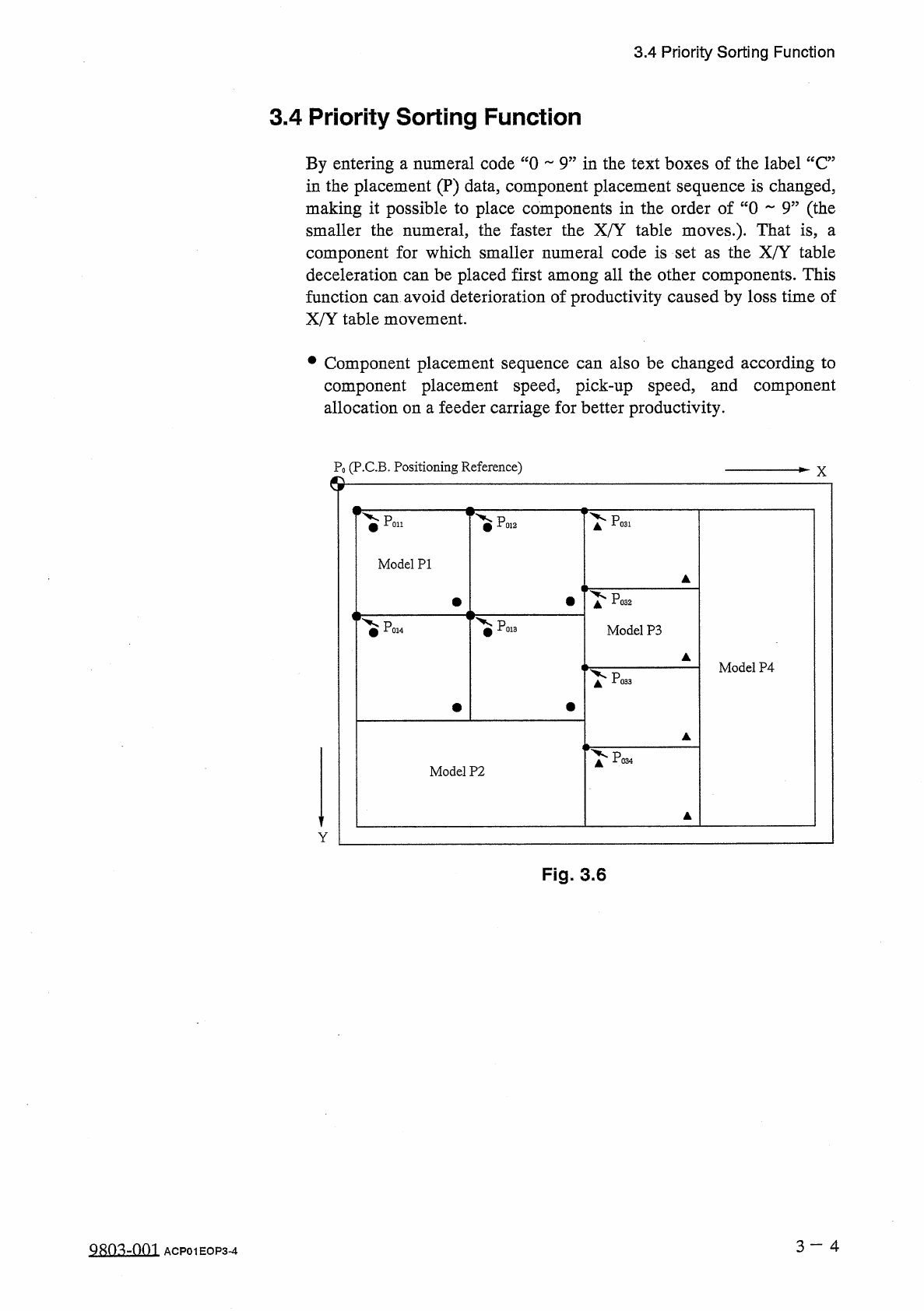
By
entering
a
numeral
code
“
0
9
”
in
the
text
boxes
of
the
label
“
C
”
in
the
placement
(
P
)
data
,
component
placement
sequence
is
changed
,
making
it
possible
to
place
components
in
the
order
of
“
0
9
”
(
the
smaller
the
numeral
,
the
faster
the
X
/
Y
table
moves
.
)
.
That
is
,
component
for
which
smaller
numeral
code
is
set
as
the
X
/
Y
table
deceleration
can
be
placed
first
among
all
the
other
components
.
This
function
can
avoid
deterioration
of
productivity
caused
by
loss
time
of
X
/
Y
table
movement
.
a
•
Component
placement
sequence
can
also
be
changed
according
to
component
placement
speed
,
pick
-
up
speed
,
and
component
allocation
on
a
feeder
carriage
for
better
productivity
.
P
0
(
P
.
C
.
B
.
Positioning
Reference
)
X
©
Poi
.
Pp
31
Poi
2
Model
PI
^
P
02
PO
!
Model
P
3
Model
P
4
Po
33
^
P
03
Model
P
2
Y
Fig
.
3.6
3
一
4
QRO
^
-
nm
ACP
01
EOP
3
-
4
3.4
Priority
Sorting
Function
Placement
Data
P
1
Placement
Data
P
2
Placement
Data
P
3
Placement
Data
P
4
Placement
Order
Placement
Order
Placement
Order
Placement
Order
Step
No
.
C
Step
No
.
C
Step
No
.
Step
No
.
CC
P
0001
P
0002
P
0003
POOCH
P
0005
P
0006
P
0007
P
0008
P
0009
P
0010
POOH
P
0012
P
0013
POOH
P
0001
P
0002
P
0003
P
0004
P
0005
P
0006
P
0007
P
0008
P
0009
P
0010
POOH
P
0012
P
0013
P
0014
P
0001
P
0002
P
0003
P
0004
P
0005
P
0006
P
0007
P
0008
P
0009
P
0010
POOH
P
0012
P
0013
P
0014
P
0001
P
0002
P
0003
POOCH
P
0005
P
0006
P
0007
P
0008
P
0009
P
0010
POOH
P
0012
P
0013
POOH
9
1
①
②
④
7
2
0
⑩
1
⑥
③
4
5
5
⑦
P
E
Q
E
00001
00002
00003
00004
00005
00001
00002
00003
00004
00005
E E
Fig
.
3.6
-
1
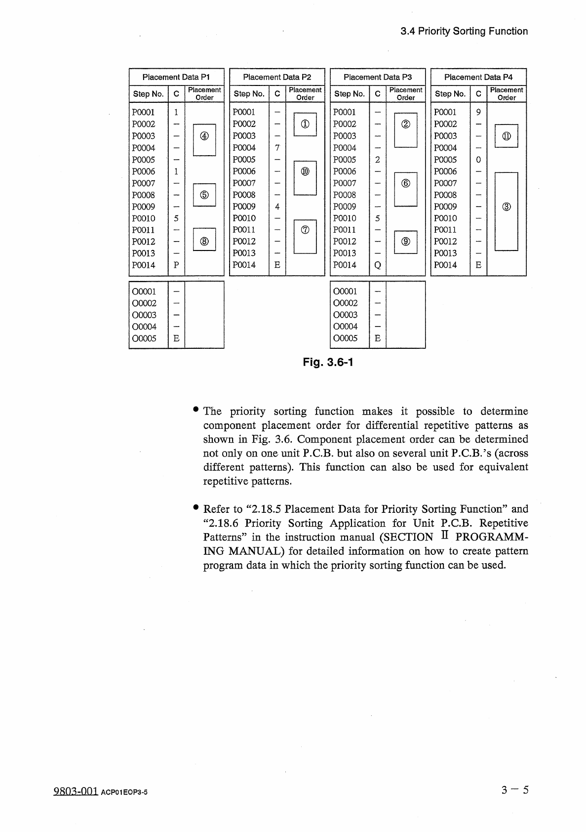
•
The
priority
sorting
function
makes
it
possible
to
determine
component
placement
order
for
differential
repetitive
patterns
shown
in
Fig
.
3.6
.
Component
placement
order
can
be
determined
not
only
on
one
unit
P
.
C
.
B
.
but
also
on
several
unit
P
.
C
.
B
/
s
(
across
different
patterns
)
.
This
function
repetitive
patterns
.
as
also
be
used
for
equivalent
can
•
Refer
to
“
2.18
.
5
Placement
Data
for
Priority
Sorting
Function
”
and
“
2.18
.
6
Priority
Sorting
Application
for
Unit
P
.
C
.
B
.
Repetitive
Patterns
”
in
the
instruction
manual
(
SECTION
D
PROGRAMM
-
ING
MANUAL
)
for
detailed
information
on
how
to
create
pattern
program
data
in
which
the
priority
sorting
function
can
be
used
.
3
~
~
5
QRO
^
-
nm
ACP
01
EOP
3
-
5
3.5
Component
Shortage
Detection
Function
3.5
Component
Shortage
Detection
Function
When
the
tape
end
of
the
same
tape
feeder
is
detected
continuously
3
times
,
the
component
shortage
warning
message
appears
in
the
text
box
of
the
label
“
MGT
.
INFO
.
”
,
indicating
that
component
shortage
error
has
occurred
at
the
feeder
(
lane
)
.
When
a
pickup
error
(
no
component
)
occurs
at
the
pertinent
lane
after
the
component
shortage
warning
message
has
appeared
in
the
text
box
of
the
label
“
MGT
.
INFO
.
”
,
this
function
regards
the
component
shortage
error
.
error
as
a
•
When
a
component
shortage
shortage
warning
message
is
also
issued
.
is
detected
,
the
component
error
•
This
function
(
“
ENABLE
box
of
the
label
“
DETECTION
MODE
”
at
the
“
SHORTAGE
OF
:
DISABLE
?
?
)
can
be
set
in
the
text
or
COMP
.
DETECTION
MODE
”
display
.
(
Hierarchical
Sequence
:
JAUTO
OPN
.
“
AUTO
OPN
.
MODE
〈
PLACEMENT
〉
,
,
Display
SUB
-
MENU
55
Display
“
SHORTAGE
OF
COMP
.
DETECTION
MODE
”
Display
)
OPERATION
MODE
3
Display
•
This
function
(
“
ENABLE
:
text
box
of
the
label
“
TAPE
END
DETECTION
”
at
the
“
COMPONENT
LIBRARY
"
display
.
3.6
Automatic
Recovery
Function
DISABLE
95
)
can
also
be
set
in
the
or
In
normal
operation
mode
,
the
machine
stops
immediately
for
component
replenishment
(
priority
)
after
a
component
shortage
error
is
detected
or
after
the
number
of
times
set
in
the
text
box
of
the
label
“
ERROR
PROCESS
DATA
1
”
or
“
ERROR
PROCESS
DATA
2
”
at
the
“
COMPONENT
LIBRARY
”
display
is
reached
.
Compared
with
the
normal
operation
mode
,
this
function
makes
the
machine
continue
to
pick
up
components
from
another
feeder
without
placing
components
from
the
feeder
where
a
component
shortage
error
has
occurred
.
After
all
P
.
C
.
B
/
s
are
finished
with
some
components
missing
,
the
feeder
carriage
returns
to
its
home
position
and
is
set
in
the
standby
mode
.
When
pick
-
up
operation
is
re
-
started
after
the
empty
feeder
is
replaced
with
a
full
feeder
(
feeder
replenished
with
components
)
,
components
are
placed
on
the
component
-
missing
areas
on
the
processed
P
.
CB
.
’
s
.
This
mode
is
called
“
Automatic
Recovery
Function
”
.
•
In
automatic
recovery
mode
,
an
error
message
appears
in
the
text
box
of
the
label
“
MGT
.
INFO
”
to
prompt
the
operator
to
prepare
components
for
replenishment
.
Note
:
The
machine
continues
to
pick
up
components
from
the
other
feeders
and
place
them
on
P
.
C
.
B
/
s
until
all
P
.
C
.
B
.
’
s
finished
.
are
3
一
6
QRn
^
-
nm
ACP
01
EOP
3
-
6