1OPERATION_.pdf - 第145页
3.7 Alternate Mode 3.7 Alternate Mode Every time a component shortage error occurs at a feeder , the machine selects the other feeders in the specified order , reducing downtime of the machine for component replenishment…
3.6
Automatic
Recovery
Function
•
When
component
shortage
errors
occur
in
different
feeder
in
a
short
interval
,
the
feeders
components
,
reducing
loss
time
for
component
replenishment
.
be
replenished
collectively
with
can
Note
:
When
a
speed
decreasing
parameter
is
set
in
the
text
box
of
the
label
“
X
/
Y
TABLE
SPEED
”
at
the
“
OPERATION
DATA
”
display
,
the
tact
time
of
the
related
components
becomes
slower
during
automatic
recovery
after
the
full
tape
feeders
are
installed
(
component
replenishment
)
.
•
Setting
of
Automatic
Recovery
Function
“
STOP
AUTO
RUN
”
or
“
PRIORITY
OF
COMP
.
”
can
be
set
in
the
text
box
of
the
label
“
RECOVERY
MODE
”
at
the
“
RECOVERY
MODE
”
display
.
(
Hierarchical
Sequence
:
“
AUTO
OPN
.
MODE
JAUTO
OPN
.
SUB
-
MENU
”
RECOVERY
〈
PLACEMENT
〉
,
,
Display
Display
—
“
OPERATION
MODE
”
Display
MODE
”
Display
)
Recovery
Mode
When
a
component
shortage
error
occurs
,
the
step
No
.
related
to
the
error
is
stored
temporarily
in
memory
.
After
that
,
the
remaining
P
.
C
.
B
.
’
s
continue
to
be
transferred
and
processed
automatically
semi
-
automatically
until
they
are
finished
.
Missing
components
placed
on
the
pertinent
P
.
C
.
B
.
’
s
later
to
avoid
producing
P
.
C
.
B
/
s
with
some
components
missing
.
Note
:
The
recovery
function
is
designed
to
work
for
production
of
good
P
.
C
.
B
.
’
s
after
any
kind
of
error
has
occurred
.
However
,
depending
on
the
contents
of
an
error
,
the
recovery
function
may
not
be
implemented
.
or
are
•
There
are
two
kinds
of
recovery
modes
一
“
Automatic
Recovery
”
and
“
Delayed
Recovery
”
.
In
actual
recovery
operation
,
each
recovery
functions
are
combined
and
activated
.
(
1
)
“
Automatic
Recovery
”
Mode
When
interposed
in
the
normal
sequence
(
placement
order
specified
in
the
pattern
program
data
)
to
perform
recovery
operation
in
a
short
time
.
occurs
,
the
steps
for
recovery
operation
are
an
error
(
2
)
“
Delayed
Recovery
”
Mode
When
the
recovery
function
should
be
applied
to
some
-
steps
,
the
function
is
not
implemented
immediately
until
the
end
of
the
pattern
program
data
.
That
is
,
the
function
is
delayed
for
component
replenishment
or
replenished
with
components
or
errors
are
processed
,
the
recovery
function
is
implemented
.
processing
.
After
feeders
are
error
3
-
7
Q
80
^
-
nm
ACP
01
EOP
3
-
7
3.7
Alternate
Mode
3.7
Alternate
Mode
Every
time
a
component
shortage
error
occurs
at
a
feeder
,
the
machine
selects
the
other
feeders
in
the
specified
order
,
reducing
downtime
of
the
machine
for
component
replenishment
.
3.7
.
1
Alternate
Feeder
Axis
Data
arranged
equally
on
feeder
carriages
#
1
and
#
2
Tape
feeders
located
on
the
right
and
left
sides
of
the
machine
.
When
a
component
are
shortage
error
or
a
chuck
error
(
continuous
errors
on
the
same
lane
)
is
detected
on
one
feeder
carriage
,
the
machine
automatically
selects
the
other
feeder
carriage
and
continues
to
produce
P
.
C
.
B
.
’
s
.
The
error
-
caused
feeder
carriage
returns
to
its
home
position
and
is
set
in
the
standby
mode
,
enabling
the
operator
to
replace
an
empty
feeder
with
a
full
one
(
component
replenishment
)
.
When
this
function
is
used
,
deterioration
of
operation
rate
can
be
prevented
.
•
When
80
(
4
Q
)
or
less
types
of
components
(
8
mm
tape
feeders
)
used
and
only
one
carriage
is
required
for
component
placement
on
all
P
.
C
.
B
/
s
,
the
alternate
feeder
axis
function
can
be
used
effectively
to
avoid
down
time
(
deterioration
of
operation
rate
)
of
the
machine
for
component
replenishment
and
maintain
total
productivity
.
are
Note
:
The
underlined
feeder
Nos
.
apply
to
TCM
-
3100
J
.
To
Implement
Alternate
Feeder
Axis
Function
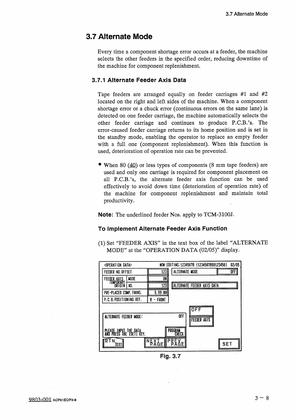
(
1
)
Set
“
FEEDER
AXIS
”
in
the
text
box
of
the
label
“
ALTERNATE
MODE
,
,
at
the
“
OPERATION
DATA
(
02
/
05
)
”
display
.
m
EDITING
:
12345678
(
1234567890123456
)
02
/
05
〈
OPERATION
DATA
〉
I
画
謹
ALTERNATE
MODE
FEEDER
NO
.
OFFSET
OMl
FEEMIIY
MODE
1
调
DALIE
臟
TE
FEEDER
AXIS
DATA
IGiN
HO
.
F
8
E
-
PLACED
COMP
.
THXNS
.
9.99
m
\
P
.
C
.
B
.
POSITIONING
REF
.
R
-
FRONT
OFF
OFF
ALTERNATE
FEEDER
MODE
:
FEEDER
AXIS
■
■
MV
l
SET
Fig
.
3.7
3
一
8
QRO
^
-
001
ACP
01
EOP
3
-
8
3.7
Alternate
Mode
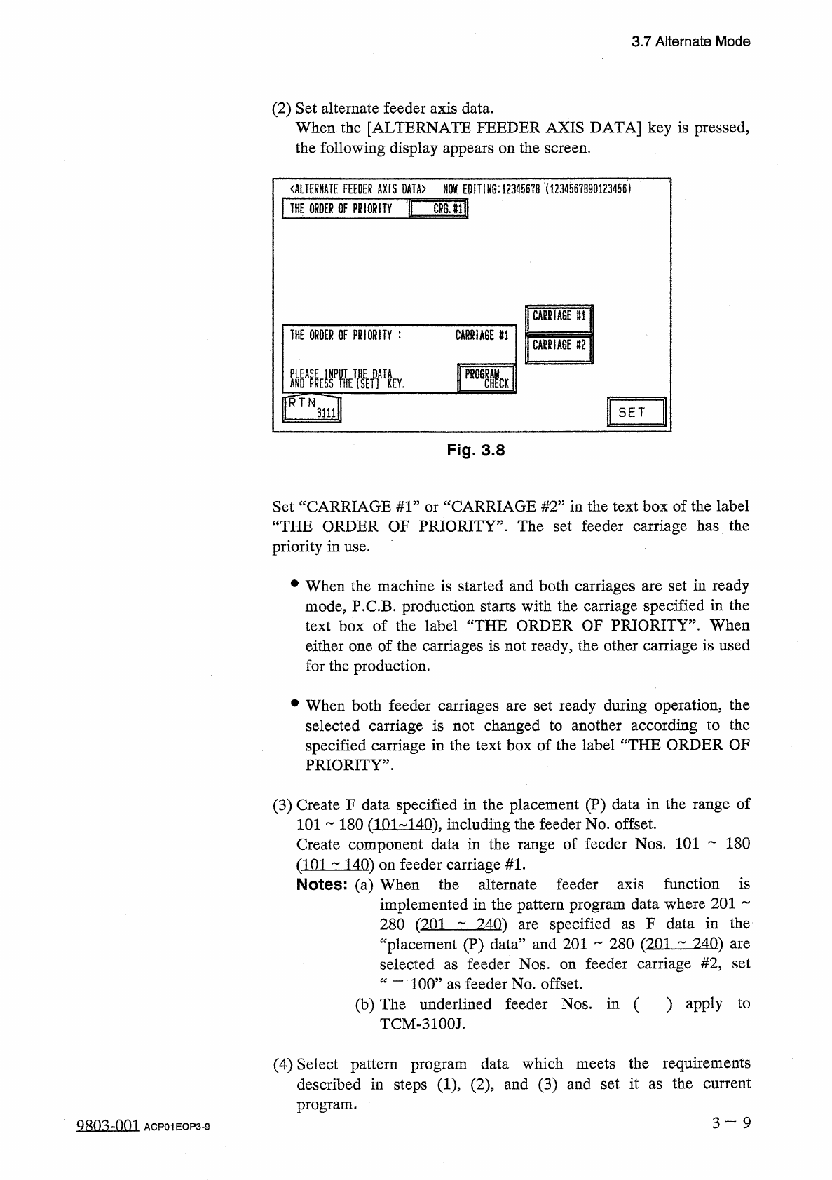
(
2
)
Set
alternate
feeder
axis
data
.
When
the
[
ALTERNATE
FEEDER
AXIS
DATA
]
key
is
pressed
,
the
following
display
appears
on
the
screen
.
〈
ALTERNATE
FEEDER
AXIS
DATA
〉
NOV
EDITING
:
12345678
(
1234567890123456
)
Mill
THE
ORDER
OF
PRIORITY
CARRIAGE
U
THE
ORDER
OF
PRIORITY
:
CARRIAGE
SI
CARRIAGE
112
ME
驟
RTN
SET
3111
Fig
.
3.8
CARRIAGE
#
2
”
in
the
text
box
of
the
label
Set
“
CARRIAGE
#
1
:
“
THE
ORDER
OF
PRIORITY
”
.
The
set
feeder
carriage
has
the
priority
in
use
.
or
#
When
the
machine
is
started
and
both
carriages
are
set
in
ready
mode
,
P
.
C
.
B
.
production
starts
with
the
carriage
specified
in
the
text
box
of
the
label
“
THE
ORDER
OF
PRIORITY
”
.
When
either
one
of
the
carriages
is
not
ready
,
the
other
carriage
is
used
for
the
production
.
•
When
both
feeder
carriages
are
set
ready
during
operation
,
the
selected
carriage
is
not
changed
to
another
according
to
the
specified
carriage
in
the
text
box
of
the
label
“
THE
ORDER
OF
PRIORITY
”
.
(
3
)
Create
F
data
specified
in
the
placement
(
P
)
data
in
the
range
of
101
~
180
(
101
-
140
)
.
including
the
feeder
No
.
offset
.
Create
component
data
in
the
range
of
feeder
Nos
.
101
180
(
101
140
)
on
feeder
carriage
#
1
.
Notes
:
(
a
)
When
the
alternate
feeder
axis
function
is
implemented
in
the
pattern
program
data
where
201
specified
F
data
in
the
280
(
201
240
)
“
placement
(
P
)
data
”
and
201
280
(
201
^
240
)
selected
are
as
are
feeder
carriage
#
2
,
set
feeder
Nos
.
on
as
“
—
100
”
as
feeder
No
.
offset
.
(
b
)
The
underlined
feeder
Nos
.
in
(
)
apply
TCM
-
3100
J
.
to
(
4
)
Select
pattern
program
data
which
meets
the
requirements
described
in
steps
(
1
)
(
2
)
and
(
3
)
and
set
it
as
the
current
program
.
3
一
9
Q
803
-
0
fi
1
ACP
01
EOP
3
-
9