1OPERATION_.pdf - 第162页
3.9 Device Information [ Relation between Nozzle Message Rate and Automatic Nozzle Bypass Function ] • The nozzle message rate ( WARNING : DECREASING OF COMP . HDLG . RATE ( FOR NOZ . ) is issued to inform the operator o…
3.9
Device
Information
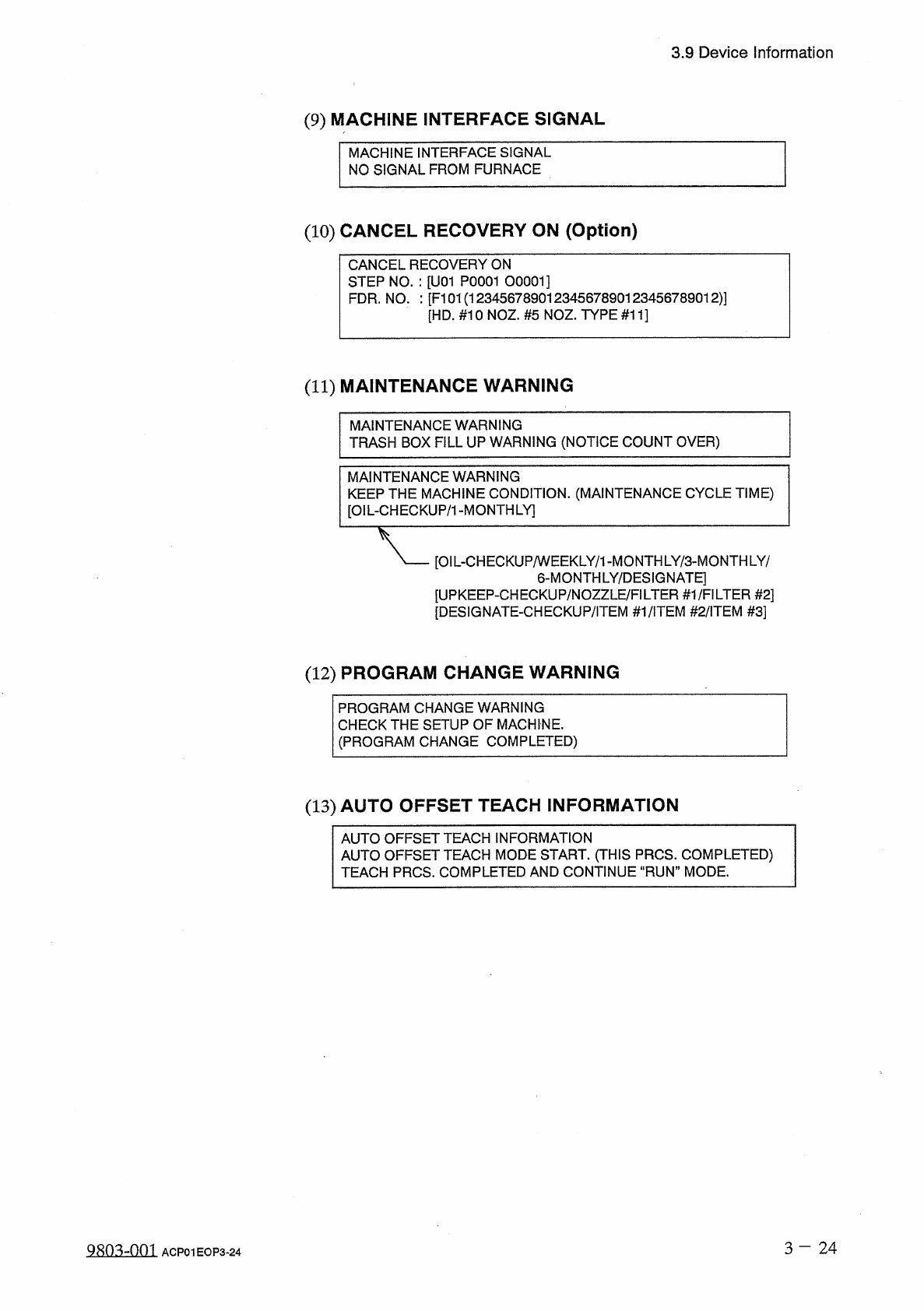
(
9
)
MACHINE
INTERFACE
SIGNAL
MACHINE
INTERFACE
SIGNAL
NO
SIGNAL
FROM
FURNACE
(
10
)
CANCEL
RECOVERY
ON
(
Option
)
CANCEL
RECOVERY
ON
STEP
NO
.
:
[
U
01
P
0001
00001
]
FDR
.
NO
.
:
[
F
101
(
12345678901234567890123456789012
)
]
[
HD
.
#
10
NOZ
.
#
5
NOZ
.
TYPE
#
11
]
(
11
)
MAINTENANCE
WARNING
MAINTENANCE
WARNING
TRASH
BOX
FILL
UP
WARNING
(
NOTICE
COUNT
OVER
)
MAINTENANCE
WARNING
KEEP
THE
MACHINE
CONDITION
.
(
MAINTENANCE
CYCLE
TIME
)
[
OIL
-
CHECKUP
/
1
-
MONTHLY
]
[
OIL
-
CHECKUP
/
WEEKLY
/
1
-
MONTH
LY
/
3
-
MONTHLY
/
6
-
MONTHLY
/
DESIGNATE
]
[
UPKEEP
-
CHECKUP
/
NOZZLE
/
FILTER
#
1
/
FILTER
#
2
]
[
DESIGNATE
-
CHECKUP
/
ITEM
#
1
/
iTEM
#
2
/
iTEM
#
3
]
(
12
)
PROGRAM
CHANGE
WARNING
PROGRAM
CHANGE
WARNING
CHECK
THE
SETUP
OF
MACHINE
.
(
PROGRAM
CHANGE
COMPLETED
)
(
13
)
AUTO
OFFSET
TEACH
INFORMATION
AUTO
OFFSET
TEACH
INFORMATION
AUTO
OFFSET
TEACH
MODE
START
.
(
THIS
PRCS
.
COMPLETED
)
TEACH
PRCS
.
COMPLETED
AND
CONTINUE
“
RUN
”
MODE
.
3
-
2 4
Q
80
^
-
nm
ACP
01
EOP
3
-
24
3.9
Device
Information
[
Relation
between
Nozzle
Message
Rate
and
Automatic
Nozzle
Bypass
Function
]
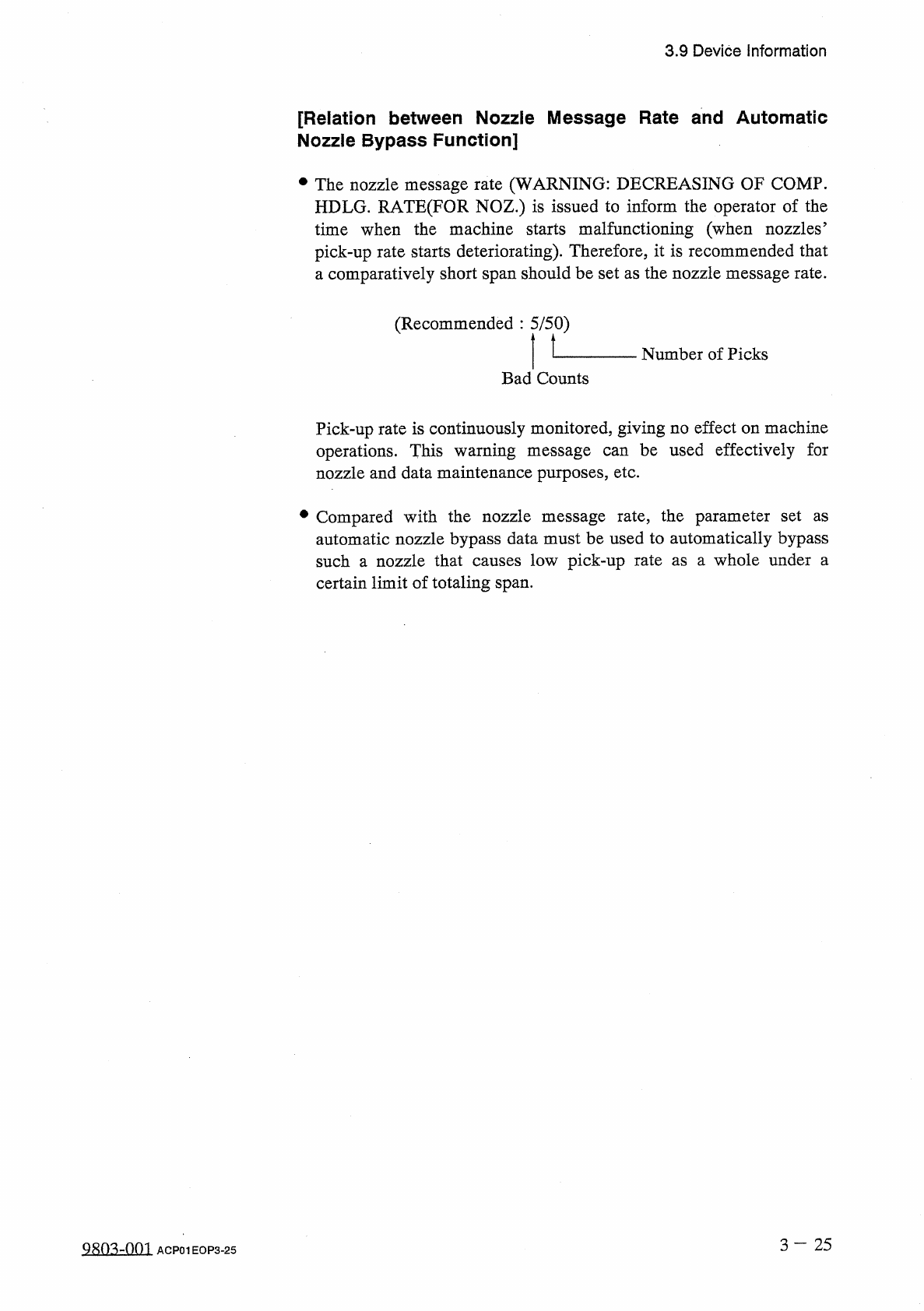
•
The
nozzle
message
rate
(
WARNING
:
DECREASING
OF
COMP
.
HDLG
.
RATE
(
FOR
NOZ
.
)
is
issued
to
inform
the
operator
of
the
time
when
the
machine
starts
malfunctioning
(
when
nozzles
’
pick
-
up
rate
starts
deteriorating
)
.
Therefore
,
it
is
recommended
that
comparatively
short
span
should
be
set
as
the
nozzle
message
rate
.
a
(
Recommended
:
5
/
50
)
Number
of
Picks
Bad
Counts
Pick
-
up
rate
is
continuously
monitored
,
giving
no
effect
on
machine
operations
.
This
warning
message
nozzle
and
data
maintenance
purposes
,
etc
.
be
used
effectively
for
can
•
Compared
with
the
nozzle
message
rate
,
the
parameter
set
automatic
nozzle
bypass
data
must
be
used
to
automatically
bypass
such
a
nozzle
that
causes
low
pick
-
up
rate
certain
limit
of
totaling
span
.
as
a
whole
under
a
as
3
—
25
Q
80
^
-
0
ni
ACP
01
EOP
3
-
25
3.10
Simplified
Packaging
Direction
Change
Function
3.10
Simplified
Packaging
Direction
Change
Function
(
Editing
of
Component
Carriage
Data
)
This
function
enables
the
continuous
operation
of
component
placement
even
during
the
following
cases
.
•
When
components
automatic
operation
,
the
same
taped
components
(
packaged
in
the
same
direction
)
as
those
used
so
far
are
not
available
.
•
Although
the
same
types
of
components
are
taped
,
they
are
packed
in
different
direction
.
•
When
a
paper
tape
should
be
used
,
an
embossed
one
is
set
.
•
Only
taped
components
packaged
in
different
direction
are
available
due
to
unavailability
or
out
of
stock
.
supplied
after
component
shortage
during
are
•
Designation
of
placement
angle
in
the
pattern
program
data
is
defined
as
an
angle
data
(
at
what
degree
a
component
should
be
rotated
)
based
upon
the
packaged
posture
of
supplied
components
.
When
components
packaged
in
different
direction
are
supplied
in
the
middle
of
operation
,
they
could
be
placed
in
the
wrong
direction
or
an
error
will
occur
in
the
component
recognition
.
Moreover
,
as
there
is
a
difference
in
pick
-
up
level
between
paper
and
embossed
tapes
,
the
pick
-
up
operation
will
be
hindered
if
adverse
tape
is
used
.
It
can
be
said
that
this
simplified
packaging
direction
change
function
is
used
to
avoid
these
deterrents
.
an
•
An
error
such
as
a
vertical
component
error
may
occur
due
to
slight
variations
in
the
thickness
of
the
same
type
of
components
.
The
components
regarded
as
thin
components
due
to
a
difference
in
constants
,
etc
.
may
be
placed
minimum
component
thickness
level
must
be
entered
as
the
component
thickness
check
data
in
the
component
library
.
It
can
be
said
that
this
simplified
packaging
direction
change
function
is
used
to
avoid
these
deterrents
.
the
P
.
C
.
B
.
Therefore
,
the
on
①
It
is
not
necessary
to
change
component
ID
names
and
component
library
data
.
②
It
is
not
necessary
to
change
the
Z
=
Theta
(
Angle
)
data
in
the
placement
data
(
P
)
.
③
While
data
(
carrier
data
“
DIR
.
’
,
,
“
TYPE
”
,
“
TAPE
END
DETECTION
”
,
COMPONENT
THICKNESS
t
,
,
,
“
VERTICAL
COMPONENT
DATA
,
,
,
and
“
COMPONENT
THICKNESS
CHECK
”
)
of
the
component
library
data
(
pertinent
component
)
defined
in
the
component
library
are
being
kept
intact
,
“
Direction
Data
’
’
,
“
Type
Data
”
,
and
“
Tape
End
Detection
Data
”
(
called
“
Switch
Data
”
and
stored
on
the
machine
side
)
are
used
in
place
of
the
library
-
defined
when
the
simplified
data
as
measure
an
emergency
packaging
direction
change
instruction
is
received
,
enabling
the
continuous
operation
of
the
machine
.
@
This
switch
data
is
temporarily
reflected
only
program
data
.
carrier
the
current
on
3
—
26
QR
01001
ACP
01
EOP
3
-
26