1OPERATION_.pdf - 第164页
3.10 Simplified Packaging Direction Change Function ⑤ When the machine is in the “ STOP : “ PAUSE ” mode , or component carriage data edit operation can be performed . Note : It is prohibited to change the component ID a…
3.10
Simplified
Packaging
Direction
Change
Function
3.10
Simplified
Packaging
Direction
Change
Function
(
Editing
of
Component
Carriage
Data
)
This
function
enables
the
continuous
operation
of
component
placement
even
during
the
following
cases
.
•
When
components
automatic
operation
,
the
same
taped
components
(
packaged
in
the
same
direction
)
as
those
used
so
far
are
not
available
.
•
Although
the
same
types
of
components
are
taped
,
they
are
packed
in
different
direction
.
•
When
a
paper
tape
should
be
used
,
an
embossed
one
is
set
.
•
Only
taped
components
packaged
in
different
direction
are
available
due
to
unavailability
or
out
of
stock
.
supplied
after
component
shortage
during
are
•
Designation
of
placement
angle
in
the
pattern
program
data
is
defined
as
an
angle
data
(
at
what
degree
a
component
should
be
rotated
)
based
upon
the
packaged
posture
of
supplied
components
.
When
components
packaged
in
different
direction
are
supplied
in
the
middle
of
operation
,
they
could
be
placed
in
the
wrong
direction
or
an
error
will
occur
in
the
component
recognition
.
Moreover
,
as
there
is
a
difference
in
pick
-
up
level
between
paper
and
embossed
tapes
,
the
pick
-
up
operation
will
be
hindered
if
adverse
tape
is
used
.
It
can
be
said
that
this
simplified
packaging
direction
change
function
is
used
to
avoid
these
deterrents
.
an
•
An
error
such
as
a
vertical
component
error
may
occur
due
to
slight
variations
in
the
thickness
of
the
same
type
of
components
.
The
components
regarded
as
thin
components
due
to
a
difference
in
constants
,
etc
.
may
be
placed
minimum
component
thickness
level
must
be
entered
as
the
component
thickness
check
data
in
the
component
library
.
It
can
be
said
that
this
simplified
packaging
direction
change
function
is
used
to
avoid
these
deterrents
.
the
P
.
C
.
B
.
Therefore
,
the
on
①
It
is
not
necessary
to
change
component
ID
names
and
component
library
data
.
②
It
is
not
necessary
to
change
the
Z
=
Theta
(
Angle
)
data
in
the
placement
data
(
P
)
.
③
While
data
(
carrier
data
“
DIR
.
’
,
,
“
TYPE
”
,
“
TAPE
END
DETECTION
”
,
COMPONENT
THICKNESS
t
,
,
,
“
VERTICAL
COMPONENT
DATA
,
,
,
and
“
COMPONENT
THICKNESS
CHECK
”
)
of
the
component
library
data
(
pertinent
component
)
defined
in
the
component
library
are
being
kept
intact
,
“
Direction
Data
’
’
,
“
Type
Data
”
,
and
“
Tape
End
Detection
Data
”
(
called
“
Switch
Data
”
and
stored
on
the
machine
side
)
are
used
in
place
of
the
library
-
defined
when
the
simplified
data
as
measure
an
emergency
packaging
direction
change
instruction
is
received
,
enabling
the
continuous
operation
of
the
machine
.
@
This
switch
data
is
temporarily
reflected
only
program
data
.
carrier
the
current
on
3
—
26
QR
01001
ACP
01
EOP
3
-
26
3.10
Simplified
Packaging
Direction
Change
Function
⑤
When
the
machine
is
in
the
“
STOP
:
“
PAUSE
”
mode
,
or
component
carriage
data
edit
operation
can
be
performed
.
Note
:
It
is
prohibited
to
change
the
component
ID
and
library
data
defined
individually
for
each
directly
because
they
component
.
are
•
When
components
having
carrier
data
different
from
that
of
the
components
being
used
are
supplied
,
it
is
necessary
to
change
the
carrier
data
of
the
components
set
on
the
pertinent
lane
.
Change
the
DATA
EDIT
”
display
.
(
Hierarchical
Sequence
:
AUTO
OPN
.
;
AUTO
OPN
.
SUB
-
MENU
”
data
at
the
“
COMPONENT
CARRIAGE
earner
MODE
<
PLACEMENT
>
Display
Display
^
“
RECOVERY
OPN
.
TEACHING
OPN
”
Display
“
COMPONENT
CARRIAGE
DATA
EDIT
”
Display
)
3
-
27
9803
-
nni
ACF
01
EOP
3
-
27
3.11
Bad
Board
Reject
Function
3.11
Bad
Board
Reject
Function
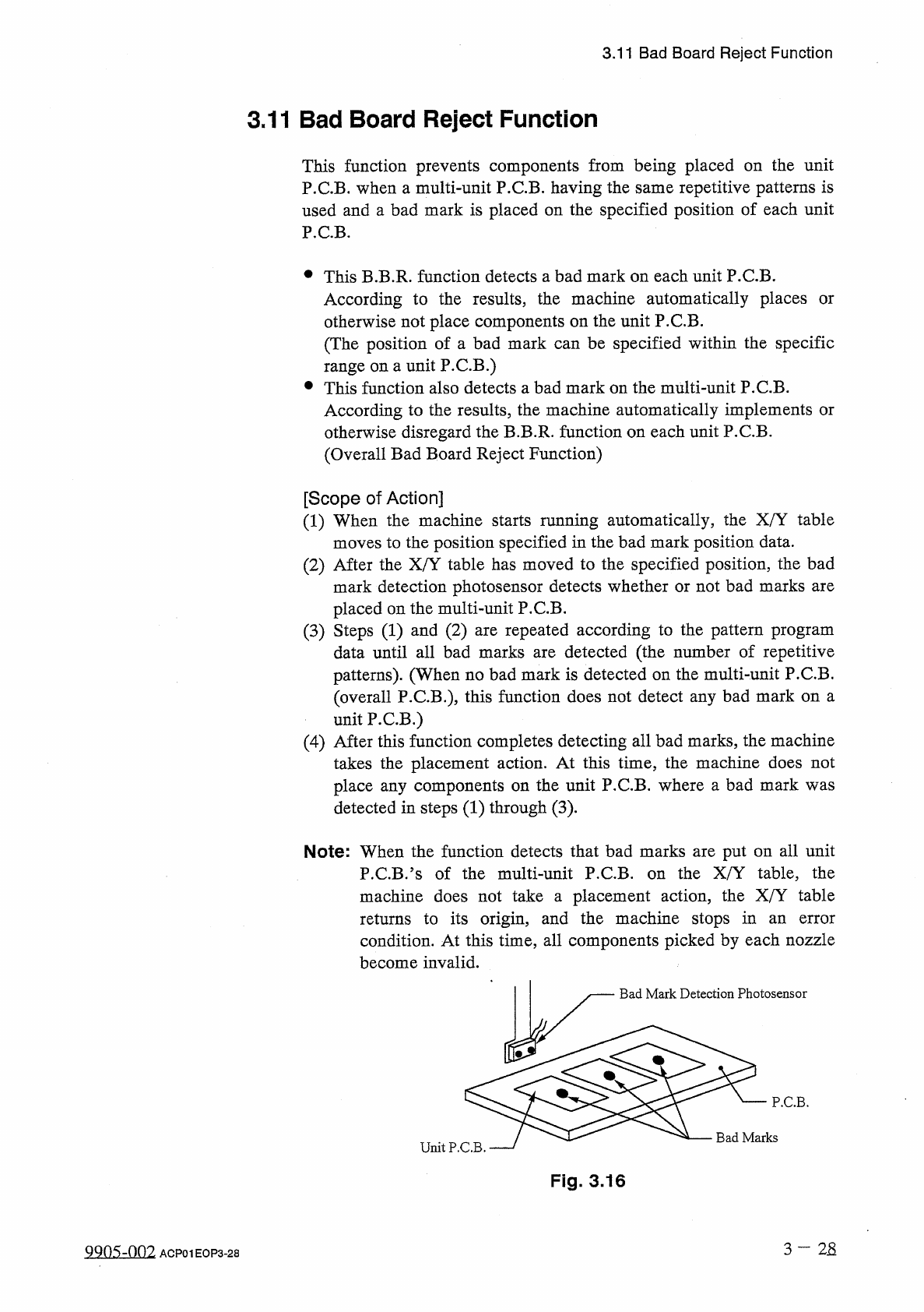
This
function
prevents
components
from
being
placed
on
the
unit
P
.
C
.
B
.
when
a
multi
-
unit
P
.
C
.
B
.
having
the
same
repetitive
patterns
is
used
and
a
bad
mark
is
placed
on
the
specified
position
of
each
unit
P
.
C
.
B
.
•
This
B
.
B
.
R
.
function
detects
a
bad
mark
on
each
unit
P
.
C
.
B
.
According
to
the
results
,
the
machine
automatically
places
otherwise
not
place
components
on
the
unit
P
.
C
.
B
.
(
The
position
of
a
bad
mark
can
be
specified
within
the
specific
range
on
a
unit
P
.
C
.
B
.
)
•
This
function
also
detects
a
bad
mark
on
the
multi
-
unit
P
.
C
.
B
.
According
to
the
results
,
the
machine
automatically
implements
or
otherwise
disregard
the
B
.
B
.
R
.
function
on
each
unit
P
.
C
.
B
.
(
Overall
Bad
Board
Reject
Function
)
or
[
Scope
of
Action
]
(
1
)
When
the
machine
starts
running
automatically
,
the
X
/
Y
table
moves
to
the
position
specified
in
the
bad
mark
position
data
.
(
2
)
After
the
X
/
Y
table
has
moved
to
the
specified
position
,
the
bad
mark
detection
photosensor
detects
whether
or
not
bad
marks
are
placed
on
the
multi
-
unit
P
.
C
.
B
.
(
3
)
Steps
(
1
)
and
(
2
)
are
repeated
according
to
the
pattern
program
data
until
all
bad
marks
are
detected
(
the
number
of
repetitive
patterns
)
.
(
When
no
bad
mark
is
detected
on
the
multi
-
unit
P
.
C
.
B
.
(
overall
P
.
C
.
B
.
)
,
this
function
does
not
detect
any
bad
mark
on
a
unit
P
.
C
.
B
.
)
(
4
)
After
this
function
completes
detecting
all
bad
marks
,
the
machine
takes
the
placement
action
.
At
this
time
,
the
machine
does
not
place
any
components
on
the
unit
P
.
C
.
B
.
where
a
bad
mark
was
detected
in
steps
(
1
)
through
(
3
)
.
Note
:
When
the
function
detects
that
bad
marks
are
put
on
all
unit
the
X
/
Y
table
,
the
P
.
C
.
B
-
?
s
of
the
multi
-
unit
P
.
C
.
B
.
machine
does
not
take
a
placement
action
,
the
X
/
Y
table
returns
to
its
origin
,
and
the
machine
stops
in
condition
.
At
this
time
,
all
components
picked
by
each
nozzle
on
an
error
become
invalid
.
Bad
Mark
Detection
Photosensor
P
.
C
.
B
.
Bad
Marks
Unit
P
.
C
.
B
.
Fig
.
3.16
3
—
2
S
ggos
-
oni
ACP
01
EOP
3
-
28