1OPERATION_.pdf - 第180页
4.2 “ AUTO OPN . MODE 〈 PLACEMENT 〉 , , Display PRODUCT PCB The following is displayed when a repetitive program is used . • PRODUCT PCB ( O - NO . Number of Specified Multi - Unit P . C . B / s ) • PLACEMENT DATA SORT /…
4.2
“
AUTO
OPN
.
MODE
<
PLACEMENT
>
”
Display
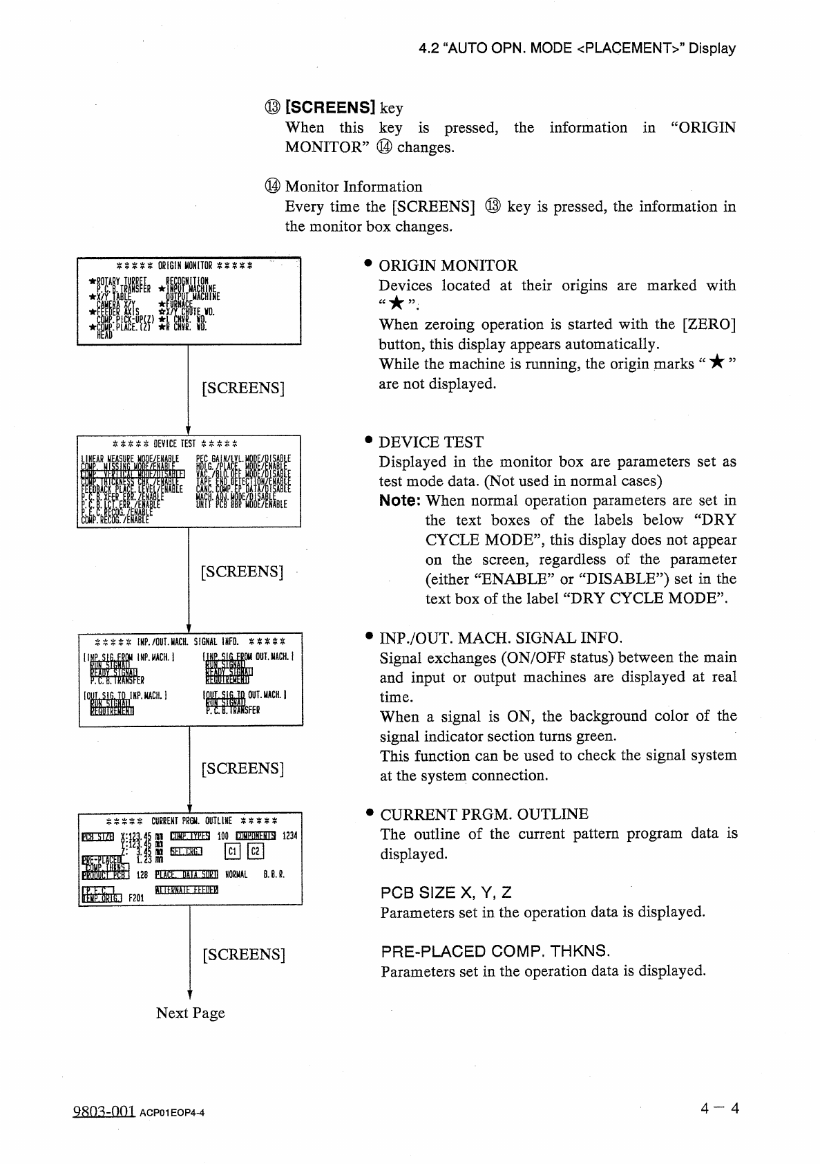
⑬
[
SCREENS
]
key
When
this
key
is
pressed
,
the
information
in
“
ORIGIN
MONITOR
”
⑭
changes
.
⑭
Monitor
Information
Every
time
the
[
SCREENS
]
⑬
key
is
pressed
,
the
information
in
the
monitor
box
changes
.
•
ORIGIN
MONITOR
Devices
located
at
their
origins
are
marked
with
ORIGIN
MONITOR
E
:
i
When
zeroing
operation
is
started
with
the
[
ZERO
]
button
,
this
display
appears
automatically
.
While
the
machine
is
running
,
the
origin
marks
are
not
displayed
.
[
SCREENS
]
•
DEVICE
TEST
Displayed
in
the
monitor
box
are
parameters
set
as
test
mode
data
.
(
Not
used
in
normal
cases
)
Note
:
When
normal
operation
parameters
are
set
in
the
text
boxes
of
the
labels
below
“
DRY
%
%
%
%
%
DEVICE
TEST
P
COMP
.
RECOG
.
/
ENABLE
LINEAR
MODE
/
ENABLE
HDLG
GAIN
/
iVLMQDE
/
DISABlE
CYCLE
MODE
”
,
this
display
does
not
appear
the
screen
,
regardless
of
the
parameter
:
DISABLE
?
?
)
set
in
the
on
[
SCREENS
]
(
either
“
ENABLE
:
text
box
of
the
label
“
DRY
CYCLE
MODE
”
.
or
•
INP
.
/
OUT
.
MACH
.
SIGNAL
INFO
.
Signal
exchanges
(
ON
/
OFF
status
)
between
the
main
and
input
or
output
machines
are
displayed
at
real
time
.
When
a
signal
is
ON
,
the
background
color
of
the
signal
indicator
section
turns
green
.
This
function
can
be
used
to
check
the
signal
system
at
the
system
connection
.
%
%
%
%
%
!
HP
.
/
OUT
.
MACH
.
SIGNAL
INFO
.
%
%
%
%
%
INP
.
MACH
.
j
醒
。
_
ii
IDf
.
SIG
.
TO
IMP
.
MCH
.
1
MM
[
SCREENS
]
•
CURRENT
PRGM
.
OUTLINE
The
outline
of
the
current
pattern
program
data
is
displayed
.
CURRENT
PPGU
.
OUTLINE
tOMF
.
IV
^
SI
100
WuN
^
ia
1234
fih
.
ckG
.
i
PflH
■
X
nn
回回
sm
128
PLACL
DAIA
M
NORMAL
8
.
B
.
R
.
B
USSDE
EEEBEfl
Ir
^
CTikt
F
20
i
PCB
SIZE
X
,
Y
,
Z
Parameters
set
in
the
operation
data
is
displayed
.
PRE
-
PLACED
COMP
.
THKNS
.
Parameters
set
in
the
operation
data
is
displayed
.
[
SCREENS
]
Next
Page
4
一
4
Q
8
n
^
-
001
ACP
01
EOP
4
-
4
4.2
“
AUTO
OPN
.
MODE
〈
PLACEMENT
〉
,,
Display
PRODUCT
PCB
The
following
is
displayed
when
a
repetitive
program
is
used
.
•
PRODUCT
PCB
(
O
-
NO
.
Number
of
Specified
Multi
-
Unit
P
.
C
.
B
/
s
)
•
PLACEMENT
DATA
SORT
/
NORMAL
/
REVERSE
•
B
.
B
.
R
.
When
the
bad
board
reject
function
is
used
,
this
appears
.
COMP
.
TYPES
The
number
of
different
component
IDs
specified
in
the
component
data
is
displayed
.
When
component
types
are
set
on
two
or
more
lanes
using
the
same
component
ID
names
,
the
number
of
the
component
types
is
regarded
as
one
type
.
COMPONENTS
The
number
of
components
to
be
placed
actually
is
displayed
.
When
“
S
”
(
Skip
)
or
“
C
”
(
Cancel
)
is
set
as
a
control
command
,
the
component
of
the
step
is
not
included
in
“
COMPONENTS
”
.
SEL
.
CRG
.
The
box
indicating
the
selected
carriage
illuminates
green
.
P
.
E
.
C
.
This
is
displayed
when
the
P
.
E
.
C
.
recognition
function
is
used
.
TEMP
.
ORIG
.
This
is
displayed
when
the
feeder
axis
temporary
origin
function
(
specified
in
the
operation
data
)
is
used
.
ALTERNATE
FEEDER
This
is
displayed
when
the
alternate
feeder
function
is
set
in
the
component
data
.
Note
:
When
the
machine
is
in
the
automatic
operation
mode
and
the
[
START
]
button
is
pressed
,
this
display
appears
automatically
.
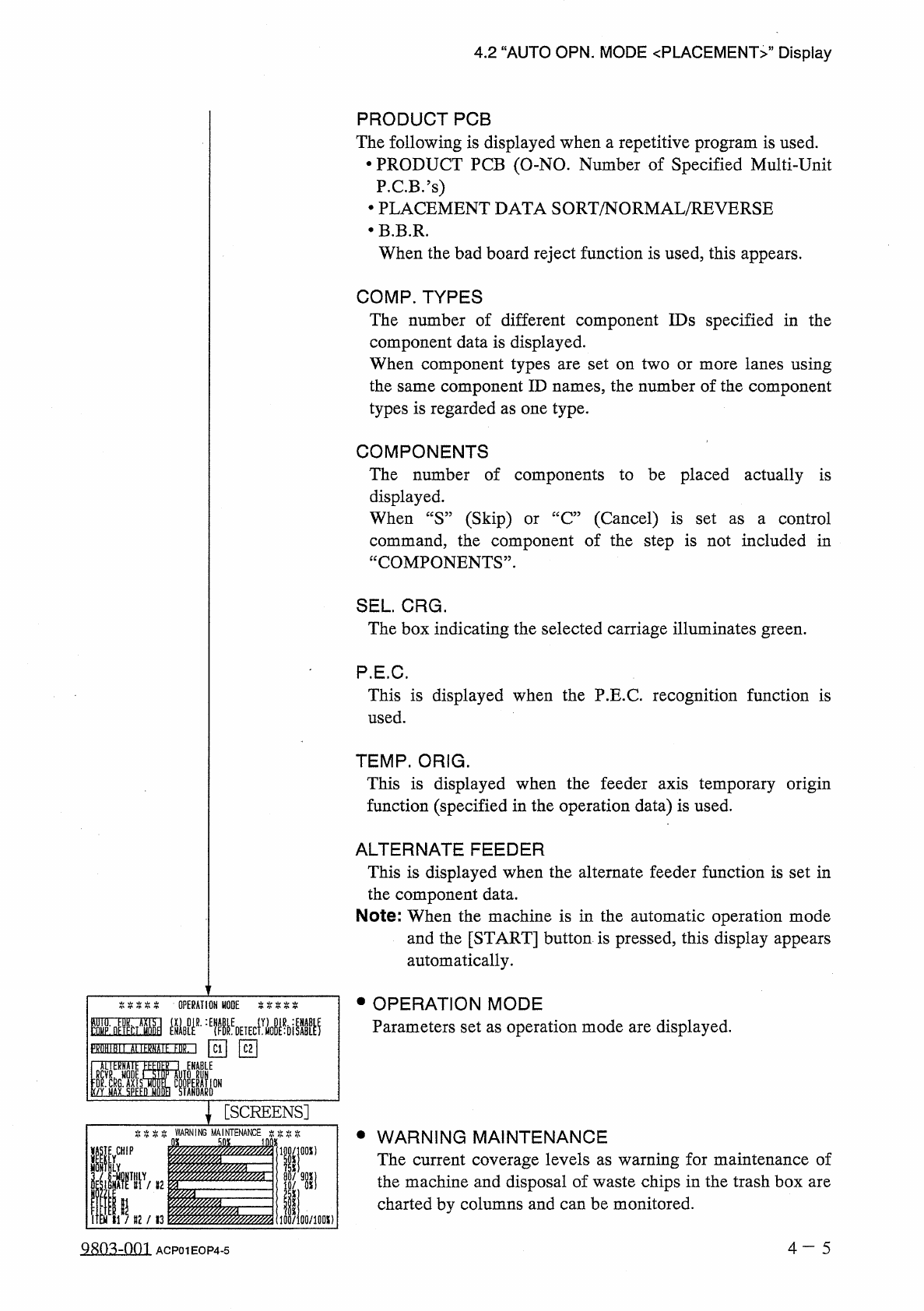
•
OPERATION
MODE
Parameters
set
as
operation
mode
are
displayed
.
IHM
■
孤墨麵
\
[
SCREENS
]
WARNING
•
WARNING
MAINTENANCE
The
current
coverage
levels
as
warning
for
maintenance
of
the
machine
and
disposal
of
waste
chips
in
the
trash
box
are
charted
by
columns
and
can
be
monitored
.
[
WHIP
iOO
/
lflOX
)
4
—
5
9803
-
001
ACP
01
EOP
4
-
5
PROGRAM
CHANGE
M A I N
n
LMENU
_
IOO
;
1
I
AUTO
OPN
.
MODE
r
<
PLACEMENI
>
1
I
\
INDIVIDUAL
FDR
.
,
ENABLE
/
DISABLE
PLACE
.
MODE
WARM
-
UP
RUNNING
MODE
SET
PA
5
S
/
P
^
(
FEEMCHANGE
-
OVER
PREPARATION
COMPLETE
)
CH
INI
,
min
Hgi
)
l
.
\
FEEDER
FEEDER
C
2
START
IND
A
CANNO
;
t
MfcNU
PRODUCT
CHANGE
OPERATION
MODE
RECALL
MESSAGES
臟
MANAGEMENT
DATA
5
11
9
10
)
(
4
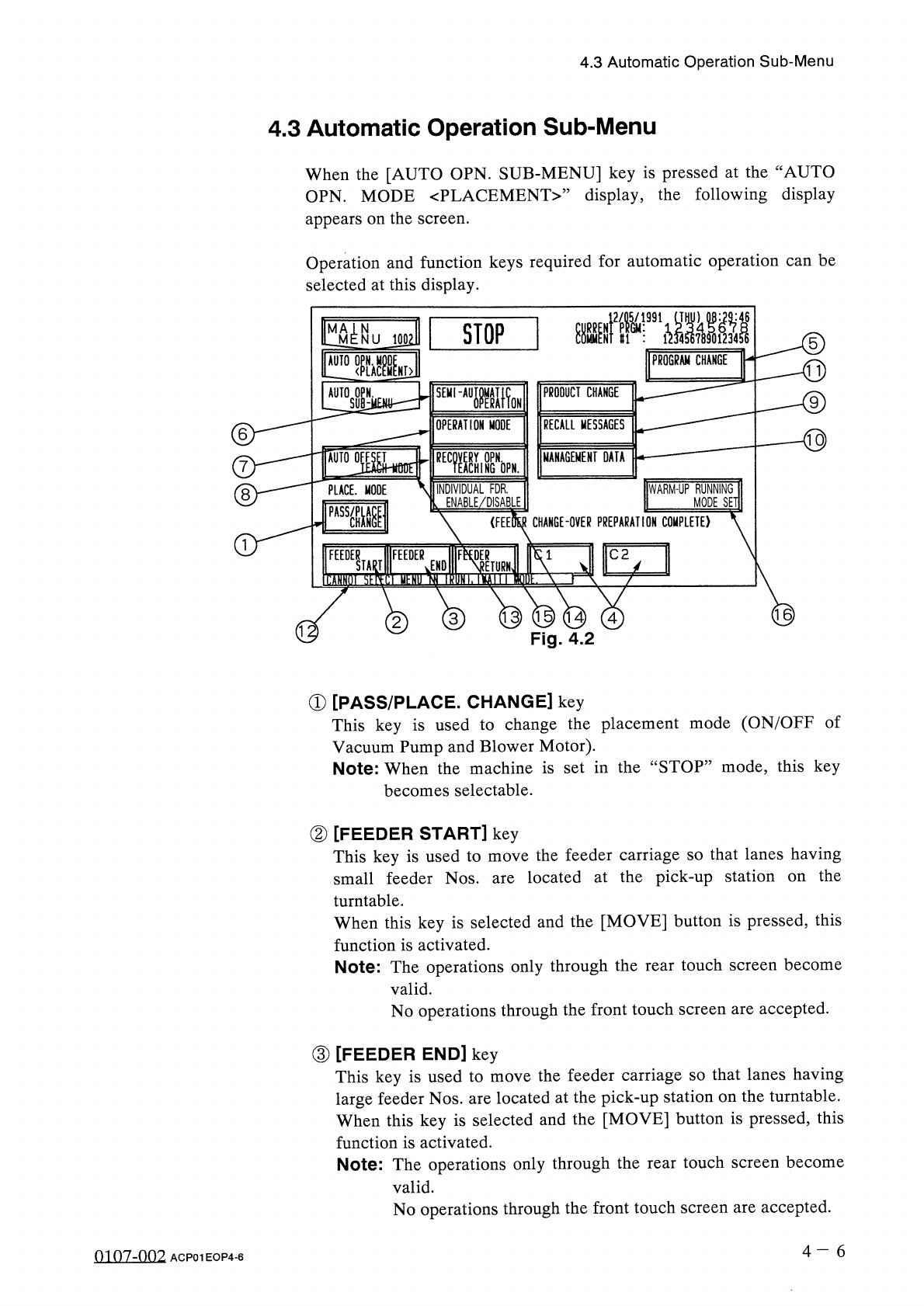
Fig
.
4.2
3
2
①
[
PASS
/
PLACE
.
CHANGE
]
key
This
key
is
used
to
change
the
placement
mode
(
ON
/
OFF
of
Vacuum
Pump
and
Blower
Motor
)
.
Note
:
When
the
machine
is
set
in
the
“
STOP
”
mode
,
this
key
becomes
selectable
.
②
[
FEEDER
START
]
key
This
key
is
used
to
move
the
feeder
carriage
so
that
lanes
having
small
feeder
Nos
.
are
located
at
the
pick
-
up
station
turntable
.
When
this
key
is
selected
and
the
[
MOVE
]
button
is
pressed
,
this
function
is
activated
.
Note
:
The
operations
only
through
the
rear
touch
screen
become
valid
.
No
operations
through
the
front
touch
screen
are
accepted
.
the
on
③
[
FEEDER
END
]
key
This
key
is
used
to
move
the
feeder
carriage
so
that
lanes
having
large
feeder
Nos
.
are
located
at
the
pick
-
up
station
on
the
turntable
.
When
this
key
is
selected
and
the
[
MOVE
]
button
is
pressed
,
this
function
is
activated
.
Note
:
The
operations
only
through
the
rear
touch
screen
become
valid
.
No
operations
through
the
front
touch
screen
are
accepted
.
4
一
6
4.3
Automatic
Operation
Sub
-
Menu
4.3
Automatic
Operation
Sub
-
Menu
When
the
[
AUTO
OPN
.
SUB
-
MENU
]
key
is
pressed
at
the
“
AUTO
OPN
.
MODE
〈
PLACEMENT
〉
”
display
,
the
following
display
appears
on
the
screen
.
Operation
and
function
keys
required
for
automatic
operation
can
be
selected
at
this
display
.
8
01
07
-
002
ACP
01
EOP
4
-
6
STOP
J
991
1
.
」
.
.
0