1OPERATION_.pdf - 第191页
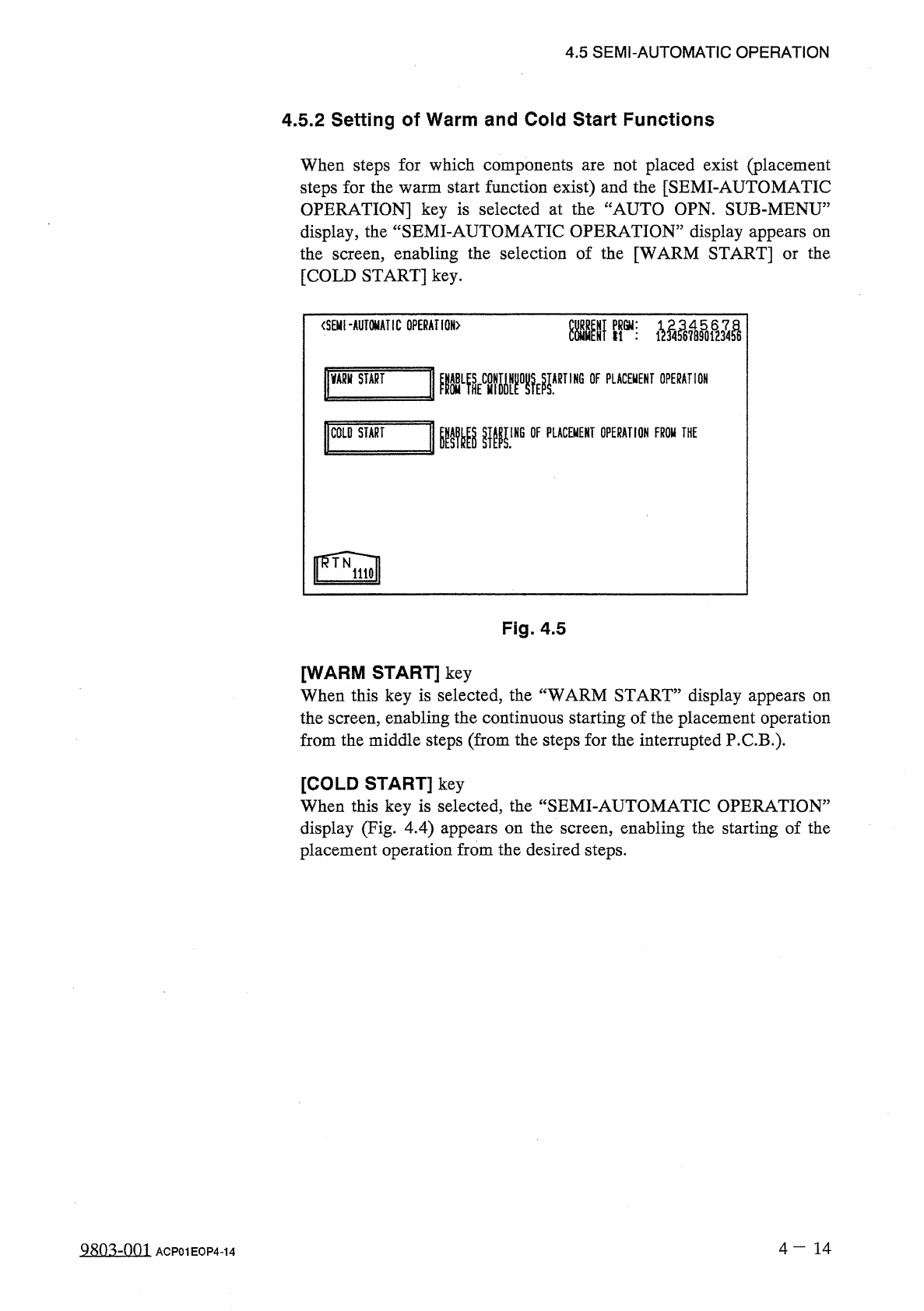
4.5 SEMI - AUTOMATIC OPERATION 4.5 . 2 Setting of Warm and Cold Start Functions When steps for which components steps for the warm start function exist ) and the [ SEMI - AUTOMATIC OPERATION ] key is selected at the “ AU…
4.5
SEMI
-
AUTOMATIC
OPERATION
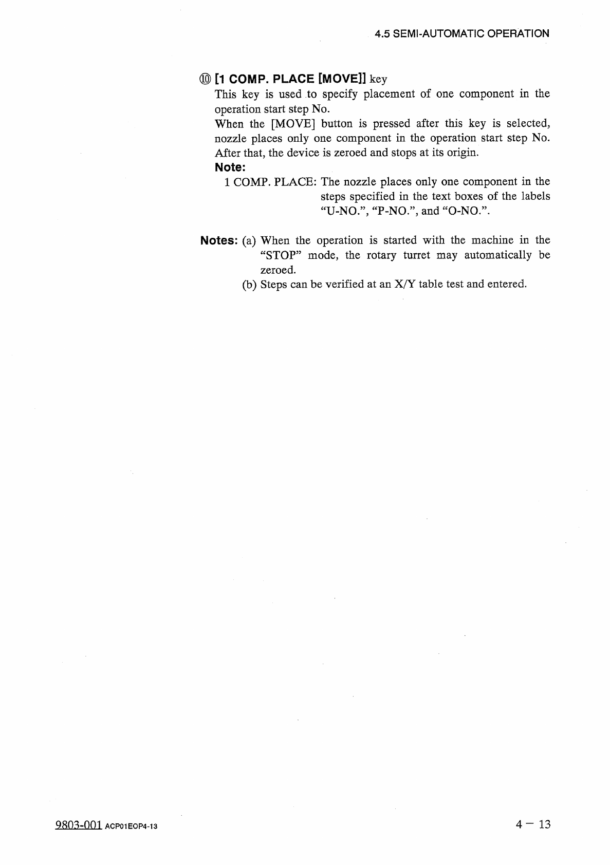
⑩
[
1
COMP
.
PLACE
[
MOVE
]
]
key
This
key
is
used
to
specify
placement
of
one
component
in
the
operation
start
step
No
.
When
the
[
MOVE
]
button
is
pressed
after
this
key
is
selected
,
nozzle
places
only
one
component
in
the
operation
start
step
No
.
After
that
,
the
device
is
zeroed
and
stops
at
its
origin
.
Note
:
1
COMP
.
PLACE
:
The
nozzle
places
only
one
component
in
the
steps
specified
in
the
text
boxes
of
the
labels
“
U
-
NO
.
”
,
“
P
-
NO
.
”
,
and
“
O
-
NO
.
”
.
Notes
:
(
a
)
When
the
operation
is
started
with
the
machine
in
the
“
STOP
”
mode
,
the
rotary
turret
may
automatically
be
zeroed
.
(
b
)
Steps
can
be
verified
at
an
X
/
Y
table
test
and
entered
.
4
-
1 3
QSQ
3
ZQQJ
ACP
01
EOP
4
-
13
4.5
SEMI
-
AUTOMATIC
OPERATION
4.5
.
2
Setting
of
Warm
and
Cold
Start
Functions
When
steps
for
which
components
steps
for
the
warm
start
function
exist
)
and
the
[
SEMI
-
AUTOMATIC
OPERATION
]
key
is
selected
at
the
“
AUTO
OPN
.
SUB
-
MENU
”
display
,
the
“
SEMI
-
AUTOMATIC
OPERATION
”
display
appears
on
the
screen
,
enabling
the
selection
of
the
[
WARM
START
]
or
the
[
COLD
START
]
key
.
not
placed
exist
(
placement
are
<
SEMI
-
AUTOMATIC
GPERAHGN
〉
Kir
;
VARH
START
ARTING
OF
PLACEMENT
OPERATION
mmw
1
COLO
START
IHG
OF
PLACEMENT
OPERATION
FROW
THE
Fig
.
4.5
[
WARM
START
]
key
When
this
key
is
selected
,
the
“
WARM
START
”
display
appears
on
the
screen
,
enabling
the
continuous
starting
of
the
placement
operation
from
the
middle
steps
(
from
the
steps
for
the
interrupted
P
.
C
.
B
.
)
.
[
COLD
START
]
key
When
this
key
is
selected
,
the
“
SEMI
-
AUTOMATIC
OPERATION
”
display
(
Fig
.
4.4
)
appears
on
the
screen
,
enabling
the
starting
of
the
placement
operation
from
the
desired
steps
.
4
一
14
a
8
Q
3
zQQl
ACP
01
EOP
4
-
14
4.5
SEMI
-
AUTOMATIC
OPERATION
4.5
.
3
WARM
START
When
the
[
WARM
START
]
key
is
pressed
at
the
“
SEMI
-
AUTOMATIC
OPERATION
”
display
,
the
following
display
appears
on
the
screen
.
<
酬
START
〉
LAST
PLACED
STEP
DATA
X
(
il
)
Y
im
)
Z
=
THETA
U
-
NO
1
FDR
,
V
C
mm
123445
*
201
P
-
NO
.
123.45
123.45
00
12345678
5
1
90
*
00
*
100.00
O
-
NO
.
100.00
000
00
1
COMPONENT
ID
1234567890123456
50
/
100
NOT
PLACED
STEP
#
CONFIRM
PLACE
,
OF
LAST
PLACED
STEP
X
/
Y
TABLE
TO
LAST
PLACE
.
M
iMQVEl
;
FULLAurolLii
隱臟
^
擺把
NOT
PLACEMENT
PLACEMENT
1
P
.
C
.
B
.
MODE
MODE
DEVICE
ORIGIN
X
/
Y
TABLMQ
ORIGIN
f
(
HOVE
!
iiil
©
®
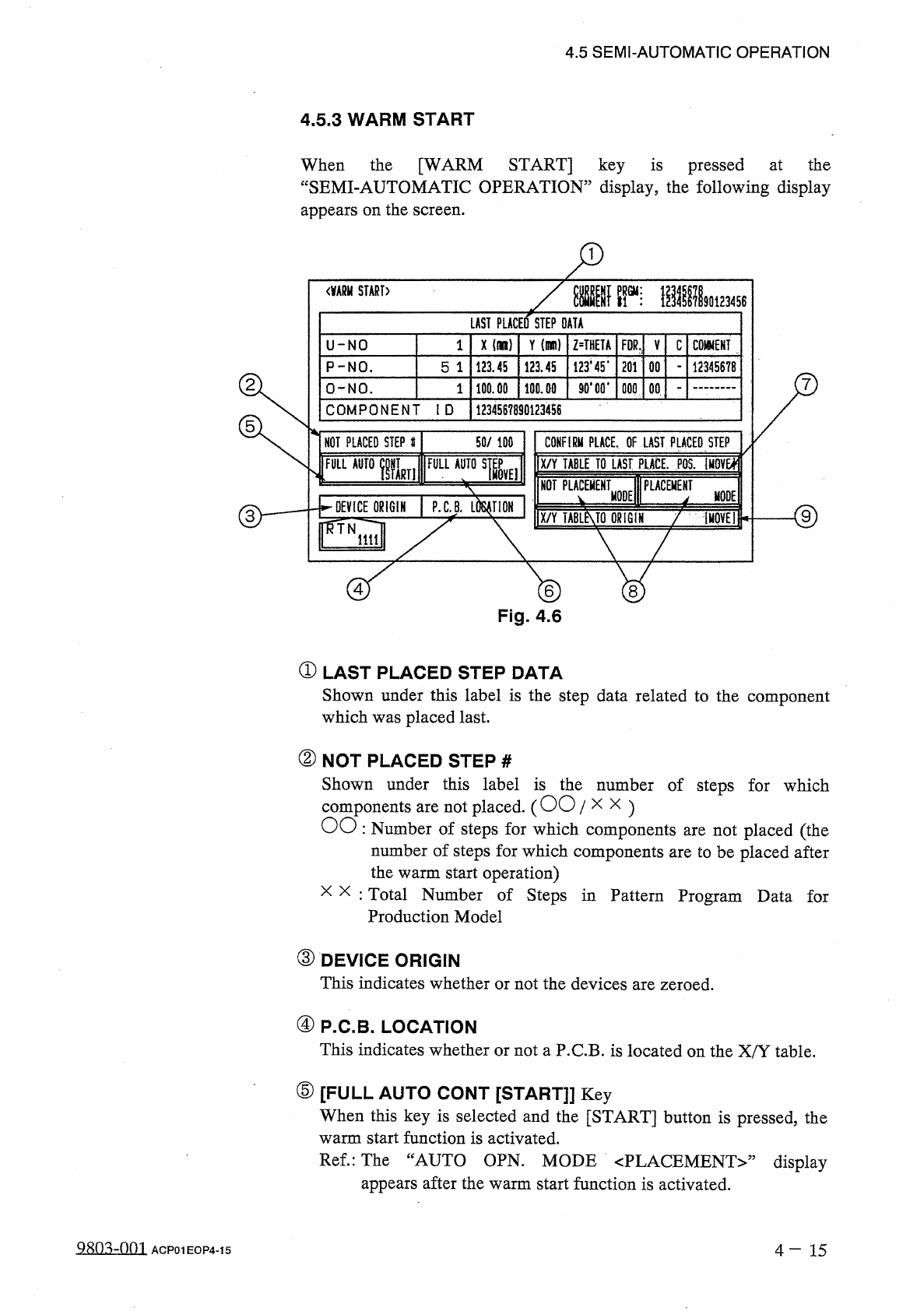
Fig
.
4.6
①
LAST
PLACED
STEP
DATA
Shown
under
this
label
is
the
step
data
related
to
the
component
which
was
placed
last
.
②
NOT
PLACED
STEP
#
Shown
under
this
label
is
the
number
of
steps
for
which
components
are
not
placed
.
(
OO
/
x
x
)
OO
:
Number
of
steps
for
which
components
are
not
placed
(
the
number
of
steps
for
which
components
are
to
be
placed
after
the
warm
start
operation
)
x x
:
Total
Number
of
Steps
in
Pattern
Program
Data
for
Production
Model
③
DEVICE
ORIGIN
This
indicates
whether
or
not
the
devices
are
zeroed
.
④
P
.
C
.
B
.
LOCATION
This
indicates
whether
or
not
a
P
.
C
.
B
.
is
located
on
the
X
/
Y
table
.
⑤
[
FULL
AUTO
CONT
[
START
]
]
Key
When
this
key
is
selected
and
the
[
START
]
button
is
pressed
,
the
warm
start
function
is
activated
.
Ref
.
:
The
“
AUTO
OPN
.
MODE
〈
PLACEMENT
〉
”
appears
after
the
warm
start
function
is
activated
.
display
4
—
1 5
ACP
01
EOP
4
-
15