1OPERATION_.pdf - 第193页
4.5 SEMI - AUTOMATIC OPERATION ⑥ [ FULL AUTO STEP [ MOVE ] ] Key When this key is selected and the [ MOVE ] button is pressed , the warm start function is activated . Ref . : The “ AUTO OPN . MODE 〈 PLACEMENT 〉 , , displ…
4.5
SEMI
-
AUTOMATIC
OPERATION
4.5
.
3
WARM
START
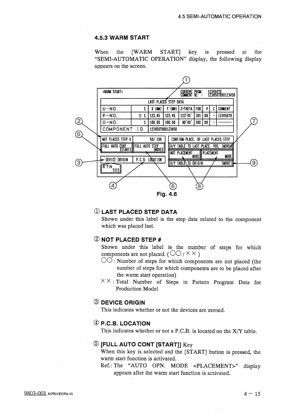
When
the
[
WARM
START
]
key
is
pressed
at
the
“
SEMI
-
AUTOMATIC
OPERATION
”
display
,
the
following
display
appears
on
the
screen
.
<
酬
START
〉
LAST
PLACED
STEP
DATA
X
(
il
)
Y
im
)
Z
=
THETA
U
-
NO
1
FDR
,
V
C
mm
123445
*
201
P
-
NO
.
123.45
123.45
00
12345678
5
1
90
*
00
*
100.00
O
-
NO
.
100.00
000
00
1
COMPONENT
ID
1234567890123456
50
/
100
NOT
PLACED
STEP
#
CONFIRM
PLACE
,
OF
LAST
PLACED
STEP
X
/
Y
TABLE
TO
LAST
PLACE
.
M
iMQVEl
;
FULLAurolLii
隱臟
^
擺把
NOT
PLACEMENT
PLACEMENT
1
P
.
C
.
B
.
MODE
MODE
DEVICE
ORIGIN
X
/
Y
TABLMQ
ORIGIN
f
(
HOVE
!
iiil
©
®
Fig
.
4.6
①
LAST
PLACED
STEP
DATA
Shown
under
this
label
is
the
step
data
related
to
the
component
which
was
placed
last
.
②
NOT
PLACED
STEP
#
Shown
under
this
label
is
the
number
of
steps
for
which
components
are
not
placed
.
(
OO
/
x
x
)
OO
:
Number
of
steps
for
which
components
are
not
placed
(
the
number
of
steps
for
which
components
are
to
be
placed
after
the
warm
start
operation
)
x x
:
Total
Number
of
Steps
in
Pattern
Program
Data
for
Production
Model
③
DEVICE
ORIGIN
This
indicates
whether
or
not
the
devices
are
zeroed
.
④
P
.
C
.
B
.
LOCATION
This
indicates
whether
or
not
a
P
.
C
.
B
.
is
located
on
the
X
/
Y
table
.
⑤
[
FULL
AUTO
CONT
[
START
]
]
Key
When
this
key
is
selected
and
the
[
START
]
button
is
pressed
,
the
warm
start
function
is
activated
.
Ref
.
:
The
“
AUTO
OPN
.
MODE
〈
PLACEMENT
〉
”
appears
after
the
warm
start
function
is
activated
.
display
4
—
1 5
ACP
01
EOP
4
-
15
4.5
SEMI
-
AUTOMATIC
OPERATION
⑥
[
FULL
AUTO
STEP
[
MOVE
]
]
Key
When
this
key
is
selected
and
the
[
MOVE
]
button
is
pressed
,
the
warm
start
function
is
activated
.
Ref
.
:
The
“
AUTO
OPN
.
MODE
〈
PLACEMENT
〉
,
,
display
appears
after
the
warm
start
function
is
activated
.
⑦
[
X
/
Y
TABLE
TO
LAST
PLACE
.
POS
.
[
MOVE
]
]
Key
When
this
key
is
selected
and
the
[
MOVE
]
button
is
pressed
,
the
X
/
Y
table
starts
moving
to
shift
the
last
placement
step
position
to
the
P
.
E
.
C
.
recognition
camera
position
.
It
can
be
checked
how
the
last
component
is
placed
.
⑧
[
NOT
PLACEMENT
MODE
]
and
[
PLACEMENT
MODE
]
Keys
[
NOT
PLACEMENT
MODE
]
Key
:
Select
this
key
when
component
is
placed
at
the
last
placement
step
position
.
[
PLACEMENT
MODE
]
Key
:
Select
this
key
when
no
component
is
placed
at
the
last
placement
step
position
.
Default
:
“
NOT
PLACEMENT
MODE
”
a
⑨
[
X
/
Y
TABLE
TO
ORIGIN
[
MOVE
]
]
Key
When
this
key
is
selected
and
the
[
MOVE
]
button
is
pressed
,
the
X
/
Y
table
is
moved
back
to
its
origin
.
[
Reference
]
When
the
warm
start
function
starts
,
the
“
AUTO
OPN
.
MODE
〈
PLACEMENT
〉
”
display
appears
on
the
screen
and
the
machine
starts
placing
components
.
After
components
placed
,
the
machine
performs
the
P
.
C
.
B
.
transfer
operation
and
starts
the
normal
automatic
operation
.
are
Notes
:
(
a
)
Component
placement
data
is
managed
for
each
individual
step
.
However
,
when
no
component
missing
data
exists
,
the
warm
start
function
cannot
be
activated
.
(
b
)
When
the
warm
start
function
starts
,
the
components
picked
up
by
the
nozzles
are
discarded
into
the
component
discharge
box
.
(
c
)
The
machine
does
not
implement
the
unit
P
.
C
.
B
.
B
.
B
.
R
.
function
.
(
d
)
The
P
.
E
.
C
.
recognition
is
re
-
performed
.
(
e
)
Before
activating
the
warm
start
function
,
check
that
any
unrequired
components
,
etc
.
,
are
not
scattered
over
the
unfinished
P
.
C
.
B
.
When
the
last
component
(
component
placed
last
)
is
placed
upright
or
bent
,
[
PLACEMENT
MODE
]
key
at
the
“
WARM
START
”
display
to
place
a
component
at
the
last
placement
step
position
.
it
and
select
the
remove
QRO
^
-
001
4
—
16
ACP
01
EOP
4
-
16
4.6
Operation
Mode
4.6
Operation
Mode
Basically
parameters
for
operation
mode
are
set
in
the
current
pattern
program
data
.
When
some
of
the
parameters
must
be
modified
according
to
situational
changes
and
the
required
menu
key
is
pressed
at
the
“
OPERATION
MODE
”
display
,
the
corresponding
display
opens
,
enabling
alteration
of
parameters
set
in
the
text
boxes
of
the
labels
such
as
“
ALTERNATE
FDR
.
AXIS
MODE
,
,
,
“
RECOVERY
MODE
”
,
etc
.
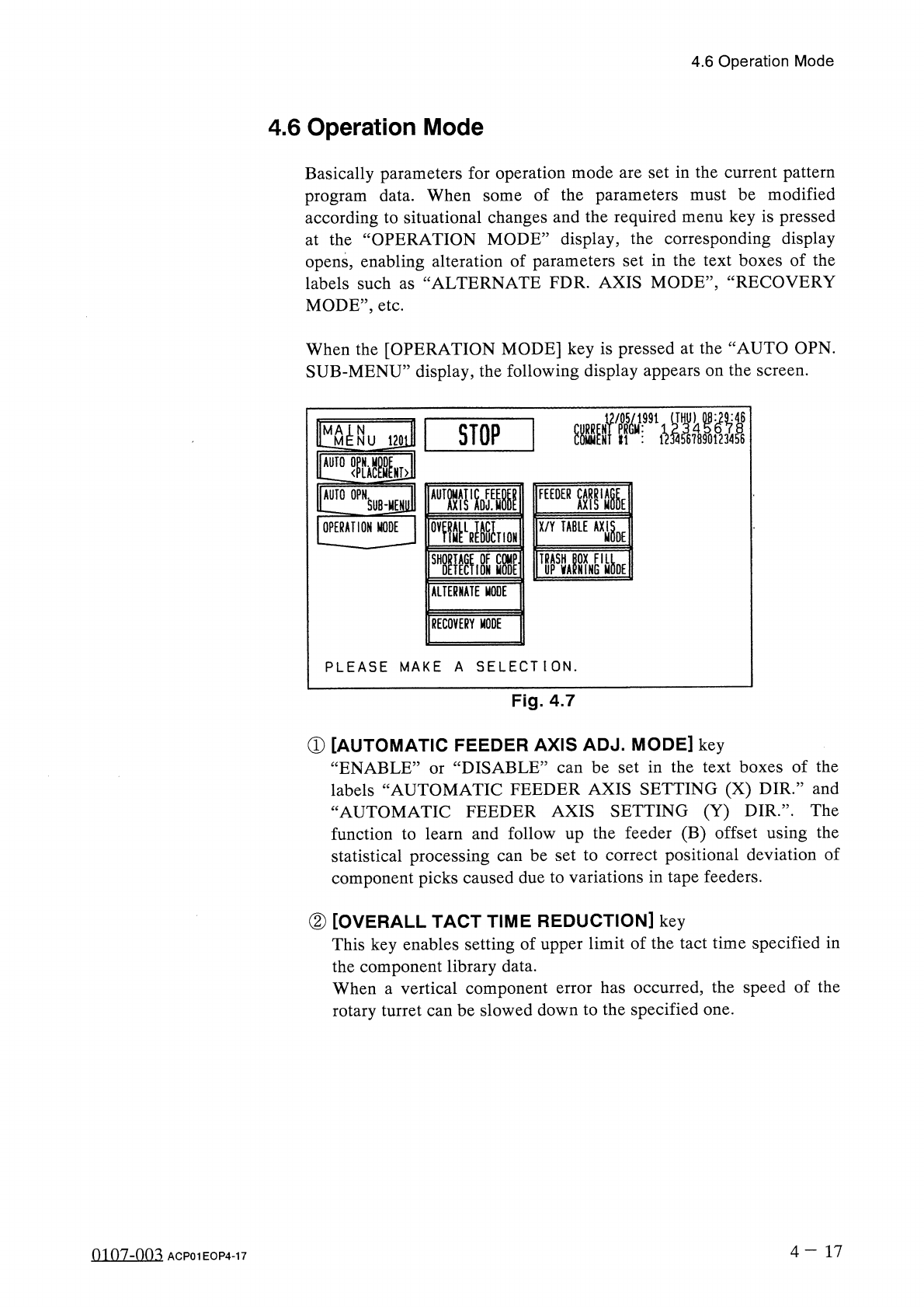
When
the
[
OPERATION
MODE
]
key
is
pressed
at
the
“
AUTO
OPN
.
SUB
-
MENU
”
display
,
the
following
display
appears
on
the
screen
.
orr
^
aii
STOP
M
N
NU
120111
FEEDER
AUTO
OPN
SUHEJUll
OPERATION
MODE
QV
^
^
LR
^
U
^
HQN
X
/
Y
TABLE
AXi
§
OE
D
?
TEC
^
!
0
N
MODE
'
酬
MOE
SHO
UP
U
ALTERNATE
MODE
RECOVERY
MODE
PLEASE
MAKE
A
SELECTION
.
Fig
.
4.7
①
[
AUTOMATIC
FEEDER
AXIS
ADJ
.
MODE
]
key
“
ENABLE
labels
“
AUTOMATIC
FEEDER
AXIS
SETTING
(
X
)
DIR
.
”
and
“
AUTOMATIC
FEEDER
AXIS
SETTING
(
Y
)
DIR
.
,
,
.
The
function
to
learn
and
follow
up
the
feeder
(
B
)
offset
using
the
statistical
processing
can
be
set
to
correct
positional
deviation
of
component
picks
caused
due
to
variations
in
tape
feeders
.
DISABLE
”
can
be
set
in
the
text
boxes
of
the
or
②
[
OVERALL
TACT
TIME
REDUCTION
]
key
This
key
enables
setting
of
upper
limit
of
the
tact
time
specified
in
the
component
library
data
.
When
a
vertical
component
error
has
occurred
,
the
speed
of
the
rotary
turret
can
be
slowed
down
to
the
specified
one
.
4
-
1 7
0107
-
003
ACP
01
EOP
4
-
17