1OPERATION_.pdf - 第196页
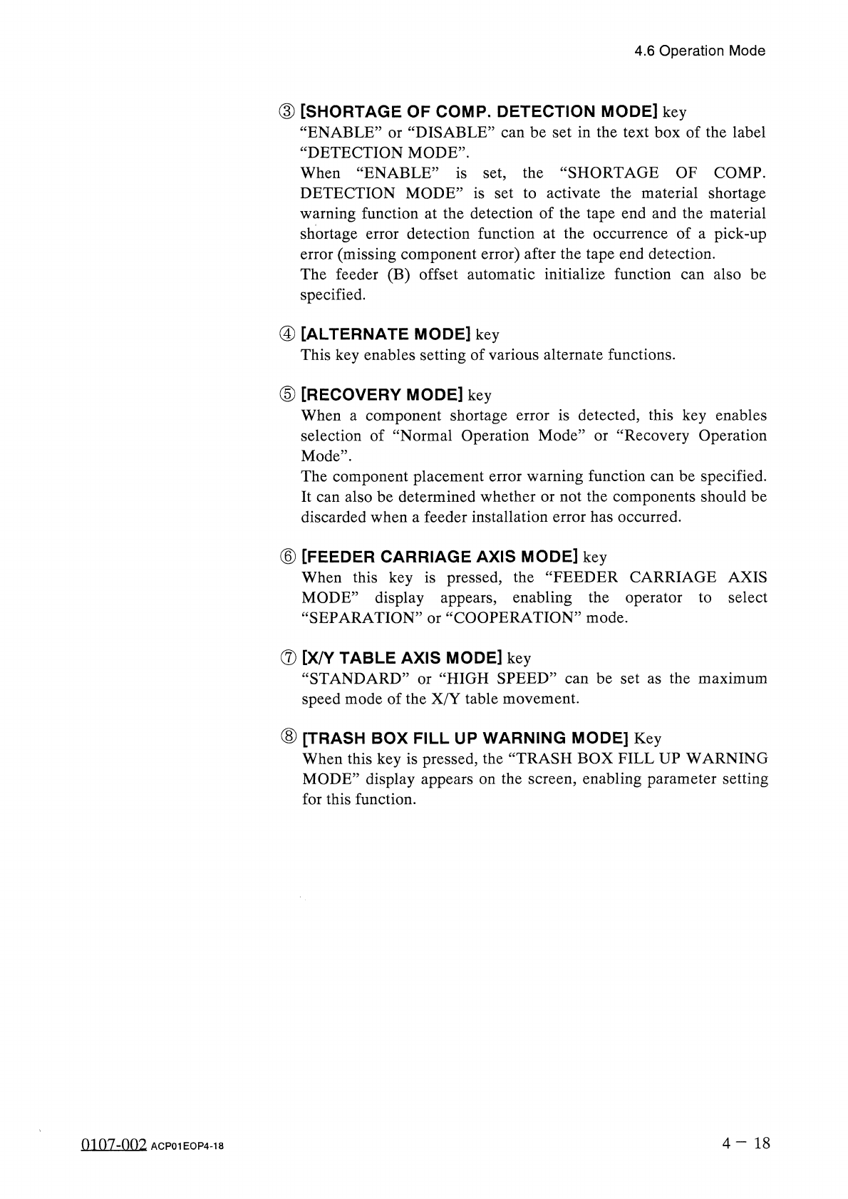
M | 6 ( AUTOMATIC FEEDER AXIS ADJUSTMENT DISABLE 11 ^ S ENABLE SET ENABLE ! C FEEDER AXIS ( X ) DIR . : DISABLE 觀 DISABLE ■ 疆 MV FQl [ S E T 4.6 Operation Mode 4.6 . 1 AUTOMATIC FEEDER AXIS ADJ . MODE • The difference be…
4.6
Operation
Mode
③
[
SHORTAGE
OF
COMP
.
DETECTION
MODE
]
key
DISABLE
55
can
be
set
in
the
text
box
of
the
label
ENABLE
DETECTION
MODE
”
.
or
When
“
ENABLE
”
is
set
,
the
“
SHORTAGE
OF
COMP
.
DETECTION
MODE
”
is
set
to
activate
the
material
shortage
warning
function
at
the
detection
of
the
tape
end
and
the
material
shortage
error
detection
function
at
the
error
(
missing
component
error
)
after
the
tape
end
detection
.
The
feeder
(
B
)
offset
automatic
initialize
function
can
also
be
specified
.
of
a
pick
-
up
occurrence
④
[
ALTERNATE
MODE
]
key
This
key
enables
setting
of
various
alternate
functions
.
⑤
[
RECOVERY
MODE
]
key
When
a
component
shortage
error
is
detected
,
this
key
enables
selection
of
“
Normal
Operation
Mode
1
Mode
"
.
The
component
placement
error
warning
function
can
be
specified
.
It
can
also
be
determined
whether
or
not
the
components
should
be
discarded
when
a
feeder
installation
error
has
occurred
.
Recovery
Operation
or
⑥
[
FEEDER
CARRIAGE
AXIS
MODE
]
key
When
this
key
is
pressed
,
the
“
FEEDER
CARRIAGE
AXIS
MODE
:
“
SEPARATION
:
display
appears
,
enabling
the
operator
to
select
COOPERATION
”
mode
.
or
⑦
[
X
/
Y
TABLE
AXIS
MODE
]
key
“
STANDARD
speed
mode
of
the
X
/
Y
table
movement
.
HIGH
SPEED
”
can
be
set
as
the
maximum
or
⑧
[
TRASH
BOX
FILL
UP
WARNING
MODE
]
Key
When
this
key
is
pressed
,
the
“
TRASH
BOX
FILL
UP
WARNING
MODE
”
display
appears
on
the
screen
,
enabling
parameter
setting
for
this
function
.
4
-
18
mn
7
-
nn
2
ACP
01
EOP
4
-
18
M
|
6
(
AUTOMATIC
FEEDER
AXIS
ADJUSTMENT
DISABLE
11
^
S
ENABLE
SET
ENABLE
!
C
FEEDER
AXIS
(
X
)
DIR
.
:
DISABLE
觀
DISABLE
■
疆
MV
FQl
[
SET
4.6
Operation
Mode
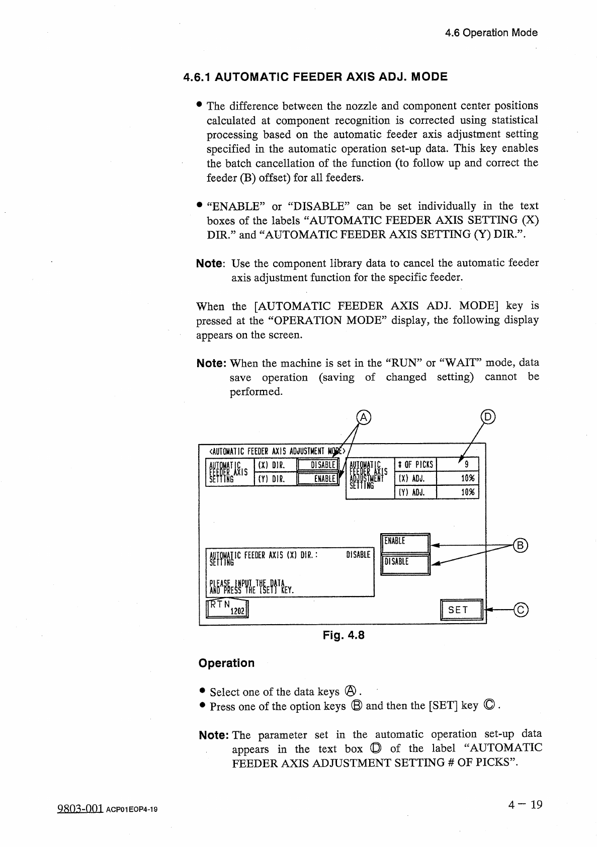
4.6
.
1
AUTOMATIC
FEEDER
AXIS
ADJ
.
MODE
•
The
difference
between
the
nozzle
and
component
center
positions
calculated
at
component
recognition
is
corrected
using
statistical
processing
based
on
the
automatic
feeder
axis
adjustment
setting
specified
in
the
automatic
operation
set
-
up
data
.
This
key
enables
the
batch
cancellation
of
the
function
(
to
follow
up
and
correct
the
feeder
(
B
)
offset
)
for
all
feeders
.
•
“
ENABLE
”
or
“
DISABLE
”
can
be
set
individually
in
the
text
boxes
of
the
labels
“
AUTOMATIC
FEEDER
AXIS
SETTING
(
X
)
DIR
.
”
and
“
AUTOMATIC
FEEDER
AXIS
SETTING
(
Y
)
DIR
.
”
.
Note
:
Use
the
component
library
data
to
cancel
the
automatic
feeder
axis
adjustment
function
for
the
specific
feeder
.
When
the
[
AUTOMATIC
FEEDER
AXIS
ADJ
.
MODE
]
key
is
pressed
at
the
“
OPERATION
MODE
”
display
,
the
following
display
appears
on
the
screen
.
WAIT
”
mode
,
data
save
operation
(
saving
of
changed
setting
)
cannot
be
performed
.
Note
:
When
the
machine
is
set
in
the
“
RUN
’
or
A
D
Fig
.
4.8
Operation
•
Select
one
of
the
data
keys
@
.
•
Press
one
of
the
option
keys
®
and
then
the
[
SET
]
key
◎
.
Note
:
The
parameter
set
in
the
automatic
operation
set
-
up
data
in
the
text
box
◎
of
the
label
“
AUTOMATIC
appears
FEEDER
AXIS
ADJUSTMENT
SETTING
#
OF
PICKS
”
.
4
一
19
Q
8
n
^
-
0
m
ACP
01
EOP
4
-
19
9
K
OF
PICKS
(
X
)
ADJ
.
10
%
(
Y
)
AOJ
.
10
%
I
4.6
Operation
Mode
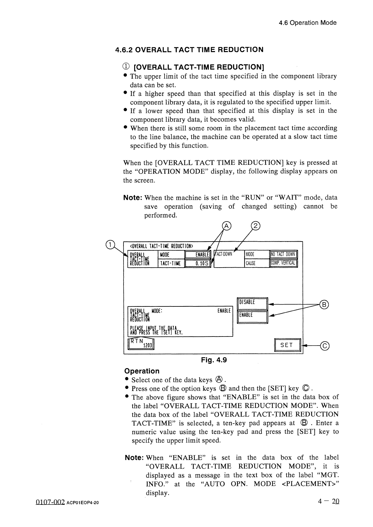
4.6
.
2
OVERALL
TACT
TIME
REDUCTION
①
[
OVERALL
TACT
-
TIME
REDUCTION
]
•
The
upper
limit
of
the
tact
time
specified
in
the
component
library
data
can
be
set
.
•
If
a
higher
speed
than
that
specified
at
this
display
is
set
in
the
component
library
data
,
it
is
regulated
to
the
specified
upper
limit
.
•
If
a
lower
speed
than
that
specified
at
this
display
is
set
in
the
component
library
data
,
it
becomes
valid
.
•
When
there
is
still
some
room
in
the
placement
tact
time
according
to
the
line
balance
,
the
machine
can
be
operated
at
a
slow
tact
time
specified
by
this
function
.
When
the
[
OVERALL
TACT
TIME
REDUCTION
]
key
is
pressed
at
the
“
OPERATION
MODE
”
display
,
the
following
display
appears
on
the
screen
.
Note
:
When
the
machine
is
set
in
the
“
RUN
”
or
“
WAIT
”
mode
,
data
save
operation
(
saving
of
changed
setting
)
cannot
be
performed
.
A
〈
OVERALL
TACT
-
TIME
REDUCTION
〉
INQ
TACT
DOWN
ENABLE
!
/
fACT
-
DOWN
MODE
lltk
MODE
COMP
.
VERTICAL
1
TACT
-
TIME
0.10
S
CAUSE
DISABLE
■
©
ENABLE
Ilk
MODE
:
ENABLE
mE
»
T
關
v
flff
.
N
.
S E T
1203
Fig
.
4.9
Operation
•
Select
one
of
the
data
keys
@
.
•
Press
one
of
the
option
keys
®
and
then
the
[
SET
]
key
O
.
•
The
above
figure
shows
that
“
ENABLE
”
is
set
in
the
data
box
of
the
label
“
OVERALL
TACT
-
TIME
REDUCTION
MODE
”
.
When
the
data
box
of
the
label
“
OVERALL
TACT
-
TIME
REDUCTION
TACT
-
TIME
”
is
selected
,
a
ten
-
key
pad
appears
at
©
.
Enter
a
numeric
value
using
the
ten
-
key
pad
and
press
the
[
SET
]
key
to
specify
the
upper
limit
speed
.
Note
:
When
“
ENABLE
”
is
set
in
the
data
box
of
the
label
“
OVERALL
TACT
-
TIME
REDUCTION
MODE
,
,
,
it
is
displayed
as
a
message
in
the
text
box
of
the
label
“
MGT
.
INFO
.
”
at
the
“
AUTO
OPN
.
MODE
〈
PLACEMENT
〉
,
,
display
.
4
-
2
Q
0107
-
002
ACP
01
EOP
4
-
20